


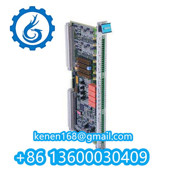


Foxboro IDP10 Series Transmitter Installation
Pre-Installation Requirements
-
Environmental Verification
- Temperature Range: -40°C to +85°C (process) / -30°C to +70°C (electronics)
- Ambient Humidity: ≤95% non-condensing
- Atmospheric Compatibility: NACE MR0175/ISO 15156
-
Process Interface
plaintextCopy Code- Flange Standard: ASME B16.5 Class 300 RF
- Material: 316L SST w/ Hastelloy C-276 diaphragm
- Seal Options: FKM (Standard) / FFKM (Aqueous HCl)
Mechanical Installation Procedure
Step 1: Mounting Configuration
plaintextCopy Code
[Remote Seal Assembly]

1. Install capillary assembly with minimum bend radius R≥75mm

2. Orientation:

   • Horizontal pipes: Sensor at 4 or 8 o'clock position

   • Vertical pipes: Flow direction → HP port

3. Support capillary every 300mm (use P-clamps CAT #FXB-SUPP-10)
[Torque Specifications]

• Flange bolts: 45 Nm ±5% (crisscross pattern)

• Process connectors: 35 Nm (DN20) / 55 Nm (DN50)
Step 2: Pressure Balancing
CRITICAL ACTIONS
- Equalize static pressure before power-up
- Bleed air via vent screws (clockwise to close)
- Confirm zero differential at startup
Electrical Installation
plaintextCopy Code
[Wiring Diagram]

Terminal +  ───[24V PSU]───[250Ω Resistor]───[DCS AI]

Terminal - ────────────────────────────────────────
[Requirements]

• Cable: BELDEN 9501 (shielded twisted pair)

• Conductor: ≥1.5mm² (16 AWG)

• Intrinsic Safety: Use Foxboro ISB07 Barrier (EEx ia)

• Grounding: <1Ω to plant earth (terminal TB1)
Terminal Connections
| Terminal | Function | Wire Color |
|---|---|---|
| + | Power Supply (18-36V DC) | Brown |
| – | Signal Return | Blue |
| G | Ground Screw | Green/Yellow |
Commissioning Sequence
-
Leak Test
- Pressurize to 110% of range limit
- Acceptable decay: ≤0.1% FS/hour
-
Zero Calibration
plaintextCopy Codea. Vent both HP/LP ports to atmosphere
b. Using HART 475: Device Setup → Trim → Sensor Trim → Zero Trim
c. Confirm output: 4.00mA ±0.02mA -
Damping Adjustment
- Default: 0.4s (adjust via HART PD 1.3.4)
- Turbulent flow recommendation: 2.5-5s

Safety & Compliance
plaintextCopy Code
EX Protection: ATEX II 1G Ex ia IIC T6 Ga

Certification: IECEx UL 17.0075X

EMC: EN 61326-1 (Industrial Immunity Level)
WARNINGS
- Never apply voltage during capacitance check (damages EEPROM)
- Avoid mounting near sources of >100V/m EMI
- Seal conduits with Foxboro CPT-32 compound
Diagnostic Indicators
| LED State | Condition | Action |
|---|---|---|
| Green solid | Normal operation | None |
| Yellow flashing (1Hz) | Communication active | HART session in progress |
| Red solid | Sensor fault (ERR 38) | Check diaphragm fill |
| Off | Power loss | Verify loop resistance |
Loop Check:
Measure resistance: + to – terminals = 28Ω ±3Ω @25°C
P0500RY FOXBORO pdf
··········································································································
Our advantages:
1. The brand new product comes with a one-year
comprehensive warranty.
2. All products undergo strict quality inspections.
3. Contact us and our team will provide competitive
quotes and procurement plans.


Reviews
Clear filtersThere are no reviews yet.