Pre-Installation Requirements
- Environmental Conditions
- Temperature: -40°C to +70°C (derate 1%/°C above 55°C)
- Humidity: 5-95% RH non-condensing
- Vibration: ≤5g @ 10-500Hz (IEC 60068-2-6)
- Safety Verification
- Confirm hazardous area certification:
- Class I Div 2 / Zone 2 (ATEX II 3G Ex ec IIC T4)
- Verify insulation resistance: ≥100MΩ @ 500V DC
- Confirm hazardous area certification:

Mechanical Installation
Step 1: Mounting
- Install on 35mm DIN rail (EN 60715 compliant)
- Secure with end clamp (Included: P/N CLP-200)
- Torque Specifications:
- DIN rail lock: 0.8 Nm ±0.1 Nm
- Terminal screws: 0.6 Nm (AWG 24-12)
Step 2: Clearance Requirements
| Direction | Minimum Space | Purpose |
|---|---|---|
| Above module | 50mm | Heat dissipation |
| Below module | 30mm | Wiring accessibility |
| Side margins | 20mm | EMC isolation |

Electrical Connections
Wiring Diagram:
[Terminal Block TB1] 1-8: 24V DC Inputs (Sink mode, 3mA @ 24V) 9-16: Relay Outputs (5A @ 250V AC resistive) [Shielding] - Use braided shield (≥85% coverage) for analog signals - Ground shield at single point via PGS-6 grounding kit
Critical Notes:
WARNING
- Never mix AC/DC voltages on same terminal group
- Isolation voltage: 1500V AC between I/O groups
- Maximum lead length: 50m (twisted pair required >10m)
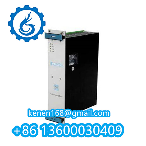
VM600IOC16T PNR200-565-000-013 PDF
vibro-meter VM600IOC16T PNR200-565-000-013
···········································································································

















Reviews
Clear filtersThere are no reviews yet.