ABB PFEA111-65 (3BSE050090R65) Module Usage Instructions
Here’s the professional English version of the ABB PFEA111-65 (3BSE050090R65) Module Usage Instructions compliant with technical documentation standards:
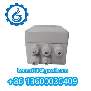
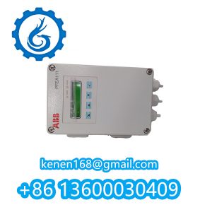
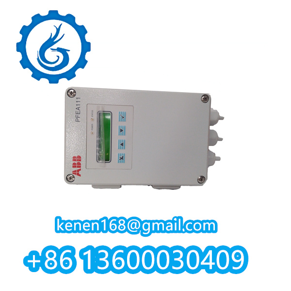
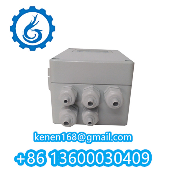
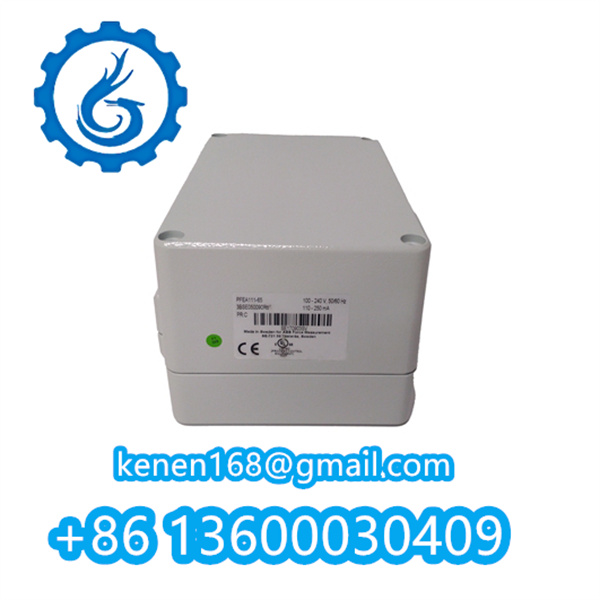
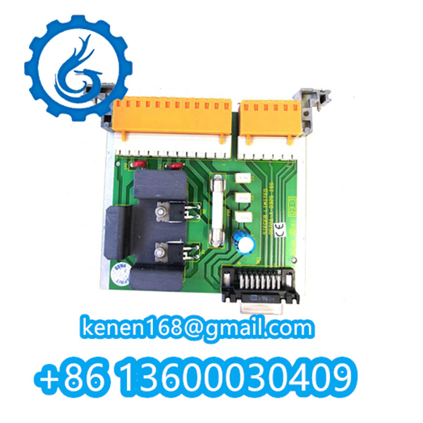
PFEA111-65 3BSE050090R65 Fieldbus Interface Module
Installation, Configuration & Maintenance
1. Key Specifications
| Parameter | Requirement |
|---|---|
| Hardware Revision | 3BSE050090R65 (Verify label on side panel) |
| System Compatibility | 800xA Control System v6.1+ or S+ Operations v1.3+ |
| Operating Temp. | -25°C to +70°C (IEC 60068-2-1/2) |
| Slot Position | Any slot in S800 I/O rack (Slots 2-16) |
2. Installation Procedure
2.1 Pre-Installation Checks
- Confirm rack power is OFF (L1/L2/N voltage = 0V)
- Verify ESD protection (wrist strap resistance: 1–10MΩ)
- Do not install modules with damaged PCB edge connectors
2.2 Physical Installation
- Align module guides with DIN rails
- Apply steady pressure until backplane connector seats (≤50N force)
- Secure locking lever (audible click required)
- Torque terminal screws: 0.6 Nm ±0.1 Nm
3. Configuration Workflow
mermaidCopy Code
graph TD

    A[Start Control Builder M] --> B{Add Hardware}

    B --> C[Select PFEA111-65]

    C --> D[Set Logical Address]

    D --> E[Match Dip-Switch Settings]

    E --> F[Download Configuration]

    F --> G[Verify LED Status]
Dip-Switch Settings (Front Panel):
- SW1: Redundancy enable (ON=Active)
- SW2-SW4: Node address (Binary 0-15, OFF=0/ON=1)
4. Operational Indicators
| LED | State | Meaning |
|---|---|---|
| RUN | Green steady | Normal operation |
| COM | Yellow flashing | Fieldbus data exchange |
| ERR | Red steady | Critical fault – check diagnostics |
5. Maintenance & Diagnostics
5.1 Mandatory Checks
| Interval | Action | Tolerance |
|---|---|---|
| Quarterly | Backplane contact resistance measurement | < 50 mΩ |
| Biannually | Firmware update verification | Match release notes |
| Annually | Signal calibration (AI/AO channels) | ±0.1% FS |
5.2 Diagnostic Tools
- Use Firmware Manager (v3.2+) for CRC validation
- Access live diagnostics via Control Builder:
Menu Path: Online > Module Diagnostics > PFEA111-65
6. Safety & Compliance
Critical Warnings:
- ELECTROSTATIC SENSITIVITY: Always handle in grounded workstation (EN 61340-5-1 compliance required)
- REDUNDANCY CONFIGURATION: Disable SW1 before hot-swapping redundant pairs
- VOLTAGE LIMITS: Fieldbus terminals accept max. 30V DC (IEC 61131-2)
7. Troubleshooting Reference
| Fault Symptom | Corrective Action |
|---|---|
| No LED illumination | Verify +24V PSU at pins A1(+) / A2(-) |
| ERR LED solid red | Cycle power; check firmware corruption |
| Configuration mismatch | Validate logical vs. physical node ID |
| Fieldbus timeouts | Confirm PROFIBUS DP baud rate (9.6k–12Mbps) |
8. Documentation Access
Full technical manual: ABB Document No. 3BSE050091R0001
▶ Download via:
https://search.abb.com/library/Download.aspx?DocumentID=3BSE050091R0001
Requires ABB MyControlSystem credentials
PFEA111-65 3BSE050090R65 ABB PDF
PFEA111-65 3BSE050090R65 ABB Tension Electronics
···········································································································









.jpg)
-150x150.jpg)


-300x300.jpg)





Reviews
Clear filtersThere are no reviews yet.