


")
")
-150x150.jpg)

- Shut down the PCD237A101 3BHE028915R0101 in accordance with the “PCD237A101 3BHE028915R0101 Lockout/Tagout Procedure” (Document No.: 3BHS600000 E22).
- Switch off MCB – Q306 to cut off the 3AC 400 V input voltage of the AC/DC converter (which supplies 24 V power).
- Wait for the IPC to complete the shutdown process (approximately 5 minutes).
- On UPS – G302, turn the selector switch labeled “Bat.-Select” to the “Service” position, then switch it back to its original value (refer to Figure 8–2). This action will interrupt the 24 V battery supply voltage; ensure the yellow “Bat.-Mode” LED turns off.
- If replacing a current transducer board, short-circuit the terminals – X900 (these are the current measurement inputs from the customer’s switchgear).
- Disconnect all cables and remove the module to be replaced (refer to Figure 8–3 for the detailed detachment procedure).
- Replace the removed module with a spare module that has an identical hardware configuration; verify that the jumper settings near the lower edge of the printed circuit board (PCB) match exactly.
- Reconnect all cables.
- Remove the short-circuits from the current measurement inputs on terminals – X900.
- Power on the transducer board by switching on MCB – Q306.
- Verify that the new module functions correctly.
.jpg)
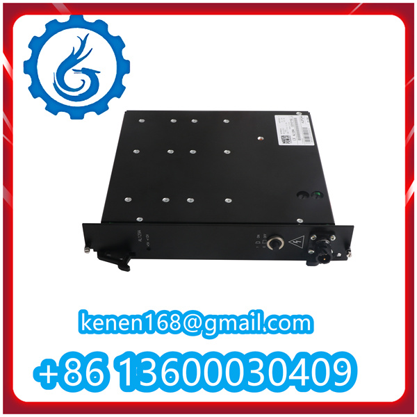
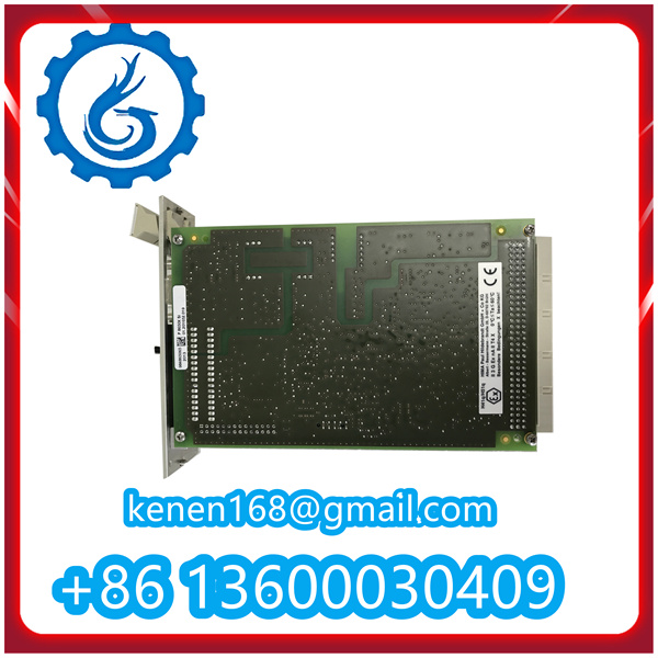
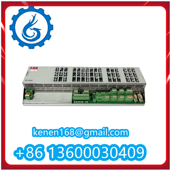
PCD237A101 3BHE028915R0101 ABB PDF
PCD237A101 3BHE028915R0101
······································································································
VIBRO-METER VM600 RPS6U PN200-582-500-013
Bently Nevada 3500/42 176449-02+128229-01
…………………………………………………………………………………………………………….


Reviews
Clear filtersThere are no reviews yet.