


1. Pre-Troubleshooting Preparation
Before starting, confirm the following to avoid unnecessary operations:
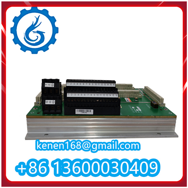
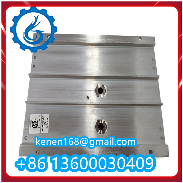
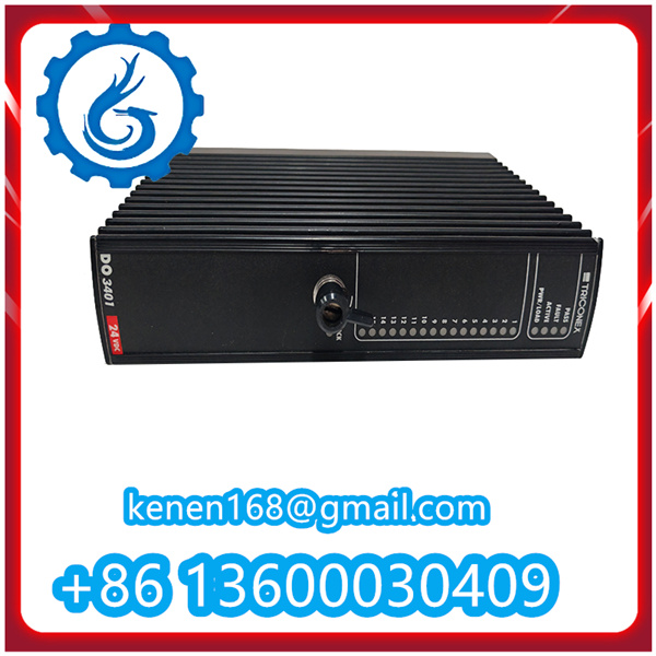
- Ensure the module’s part number (check the label on the module) matches the system configuration (verify via TRICONEX TriStation 1131 software).
- Power off the SIS chassis or isolate the DO3401 module (per lockout/tagout [LOTO] procedures) to prevent electrical hazards.
- Gather tools: Multimeter (for voltage/current measurement), insulated wire strippers, TRICONEX TriStation 1131 software (installed on a configured PC), and the module’s official technical datasheet.
2. Troubleshooting Common Fault Scenarios
Scenario 1: No Output Signal from a Specific Channel
If a connected actuator (e.g., solenoid valve) fails to respond, follow these steps:
- Check Channel Status via TriStation 1131 Software:
- Connect the PC to the TRICONEX SIS via Ethernet. Open TriStation 1131 and navigate to the DO3401 module’s “Diagnostics” tab.
- Verify if the channel is set to “Active” (output command from the controller) or “Faulted” (module self-diagnosis triggers a fault).
- If the channel shows “Faulted” (e.g., “Over-Current Fault” or “Short-Circuit Fault”), proceed to Step 2. If it shows “Active” but no physical output, move to Step 3.
- Inspect Field Wiring and Actuators:
- Power off the module. Disconnect the field wiring from the faulty channel’s terminals (refer to the module’s wiring diagram).
- Use a multimeter to check for short circuits (between the output terminal and ground) or open circuits (in the actuator’s power loop).
- Test the actuator independently: Supply 24 VDC (matching the module’s output rating) directly to the actuator. If the actuator still does not work, replace the actuator; if it works, the fault lies with the module or wiring.
- Verify Module Channel Output with Multimeter:
- Power on the module and send an “Active” command to the faulty channel via TriStation 1131.
- Measure the voltage between the channel’s output terminal and the common (COM) terminal using a multimeter (set to DC voltage mode).
- Normal reading: 19–30 VDC (matches the module’s output voltage range). If no voltage is detected:
- Check if the channel is isolated (DO3401 supports channel-to-channel isolation; a single channel fault rarely affects others).
- If the channel remains inactive, reset the module (via TriStation 1131: “Module Reset” function) or replace the module (if reset fails).
Scenario 2: Module Fails to Communicate with the SIS Controller
If the DO3401 is not detected in TriStation 1131 or shows “Loss of Communication”:
- Check Backplane Connection:
- Power off the SIS chassis. Remove the DO3401 module and inspect the backplane connector (gold pins) for dust, corrosion, or bent pins.
- Clean the connector with a dry, lint-free cloth (do not use liquids). Reinsert the module firmly until it clicks into place.
- Verify Power Supply to the Module:
- Use a multimeter to measure the voltage at the module’s power input terminals (labeled “V+” and “V-”).
- Normal reading: 22–26 VDC (24 VDC ±10%). If no voltage is detected:
- Check the redundant power supply unit (PSU) of the SIS chassis (TRICONEX modules use redundant power for fault tolerance).
- Inspect the power cables for loose connections or damage; replace faulty cables if needed.
- Check Firmware and Software Compatibility:
- In TriStation 1131, navigate to “System Information” and confirm the DO3401’s firmware version matches the controller’s firmware (incompatible versions cause communication failures).
- If a mismatch exists, update the module’s firmware via TriStation 1131 (follow TRICONEX’s firmware update guide to avoid corruption).
Scenario 3: False Over-Current/Short-Circuit Alarms
If the module triggers frequent false alarms for “Over-Current” or “Short-Circuit” (but no actual fault exists):
- Verify Current Limits in Software:
- Open TriStation 1131 and check the “Channel Configuration” for the faulty channel. Confirm the “Over-Current Threshold” is set correctly (default: 1.2x the module’s continuous current rating, typically 1.2 A for DO3401).
- Adjust the threshold if it was incorrectly modified (do not exceed the module’s maximum current capacity).
- Check for Electrical Noise Interference:
- Industrial environments with high vibration or heavy machinery may cause electrical noise. Ensure the field wiring is shielded (per TRICONEX’s wiring guidelines) and separated from high-voltage cables (minimum distance: 30 cm).
- Install a surge protector (compatible with 24 VDC circuits) on the actuator’s power loop to suppress transient voltage spikes.
- Test Module with a Known-Good Load:
- Disconnect the faulty channel’s field wiring and connect a resistive load (e.g., 24 Ω, 1 A rated) to the channel’s output terminals.
- Send an “Active” command via TriStation 1131. If the false alarm persists, the module’s current-sensing circuit is faulty; replace the module.
DO3401 TRICONEX PDF
········································································································


Reviews
Clear filtersThere are no reviews yet.