


































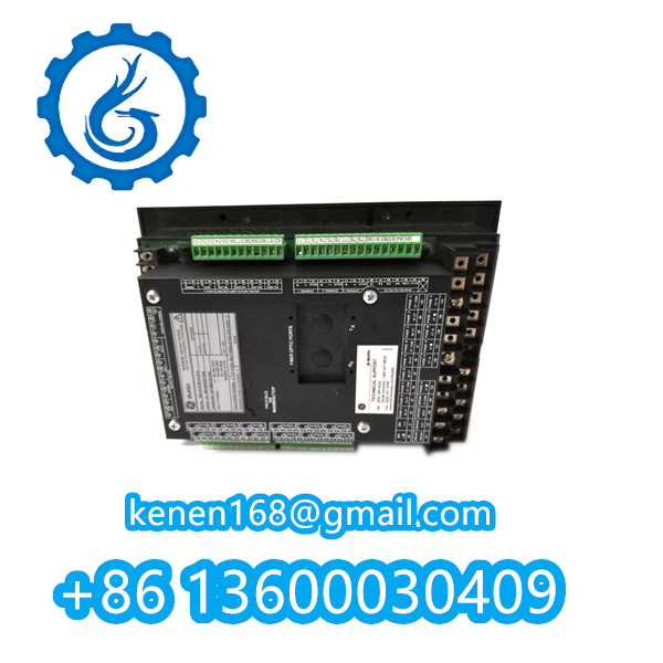

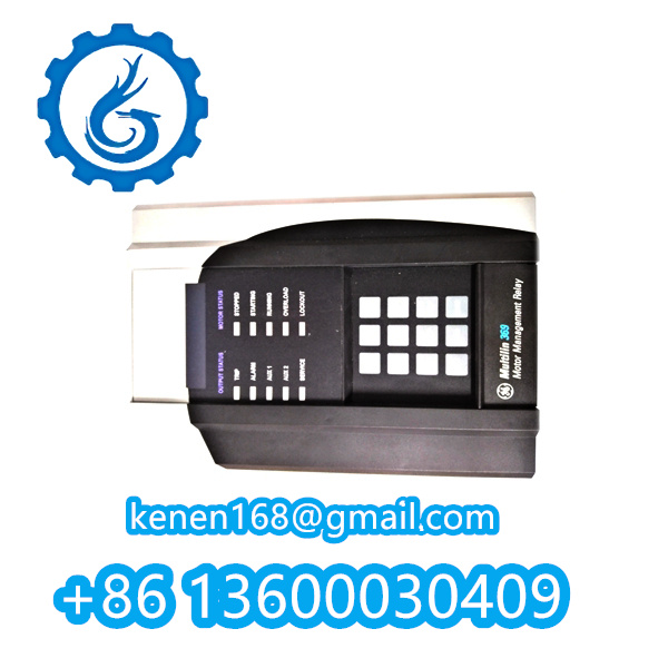
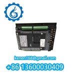
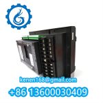



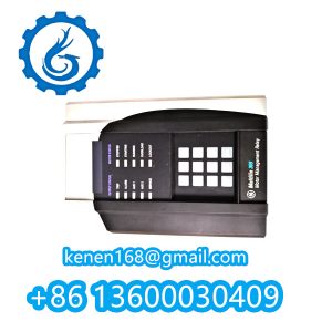
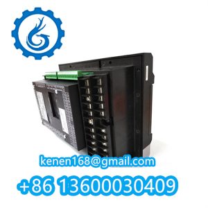
GE Multilin 369-HI-R-M-0-P1-0-E Motor Relay Commissioning Protocol
1. Pre-Commissioning Safety
Critical Measures:
- De-energize motor circuit (NFPA 70E Category 3 PPE required)
- Verify relay label: “369-HI-R-M-0-P1-0-E” (HI = High-Impedance Diff, P1 = Modbus RTU)
- Confirm CT ratios match settings (e.g., 300:5 differential CTs)
2. Hardware Verification
| Component | Check Procedure | Acceptance Criteria |
|---|---|---|
| CT Connections | Insulation resistance test (2500V DC) | >100 MΩ (phase-ground) |
| Control Power | Measure Terminals L1/L2 | 110-240VAC ±10% (<2% THD) |
| Binary Inputs | Dry contact closure test (TB3) | Status change <15ms in EnerVista |
► Use GEK-113487 test harness for CT injection
3. Relay Initialization
Front Panel Sequence:
mermaidCopy Code
graph LR

    A[Press ENTER 3s] --> B[Initialize Settings]

    B --> C[Select: Factory Defaults?]

    C --> D[Confirm with SELECT key]

    D --> E[Wait for STAT LED green]
Warning: Initialization erases custom settings!
4. Differential Protection Calibration
Slope Characteristic Test:
- Inject 20% I<sub>n</sub> at Restrained Input (R)
- Inject 15% I<sub>n</sub> at Operate Input (O)
- Verify no trip (Slope 1 = 15% typical)
- Repeat at 100% I<sub>n</sub> with 60% I<sub>n</sub> on O (Trip should occur @ Slope 2)
Settings:
textCopy Code
DIFF PICKUP: 0.3 x FLA

SLOPE 1: 15% │ SLOPE 2: 45%

BREAKPOINT: 4 x CT
5. Communication Setup (Modbus RTU)
| Parameter | Setting | Verification Tool |
|---|---|---|
| Baud Rate | 19.2 kbps | ModScan read holding reg |
| Parity | Even | CRC error count = 0 |
| Address | DIP Switch 1-5 (e.g., 00101) | Ping via RS-485 converter |
| Register Map | 4xxxx (Motor status) | EnerVista 369 SR3 software |
► Termination resistor: 120Ω only for end-of-line units
6. Dynamic Functional Tests
Simulated Fault Sequence:
- Phase Loss: Disconnect L1 input → Trip in <100ms (Setpoint: 0.5s)
- Locked Rotor: Inject 600% FLA → Trip @ 8s (Curve: I<sup>2</sup>t = ON)
- Ground Fault: Apply 25mA @ GF input → LED alarm (Pickup = 20mA)
Waveform Capture:
- Trigger via front-panel RECORD button
- Download .COMTRADE via USB (FTP://192.168.1.369)
7. Final Validation
| Documentation | Requirements |
|---|---|
| Test Record Sheet | GE Form F6501-089 (signed by P.E.) |
| Setting Report | EnerVista printed with password protection |
| IRIG-B Sync Verification | ±1ms accuracy (Terminal TB4) |
8. Critical Warnings
- Never test differential protection without CT shorting blocks engaged
- HI model requires minimum 15mA biasing current (Check with clamp meter)
- Modbus address conflict voids UL 1053 certification
···········································································································


Reviews
Clear filtersThere are no reviews yet.