


")
")

Pre-Test Requirements
- Environment Setup
- Ensure the test bench meets ABB’s standard operating conditions (23±5°C, <60% humidity).
- Verify grounding connections to prevent electrostatic discharge (ESD).
- Hardware Preparation
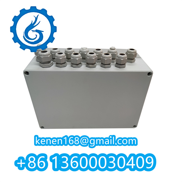
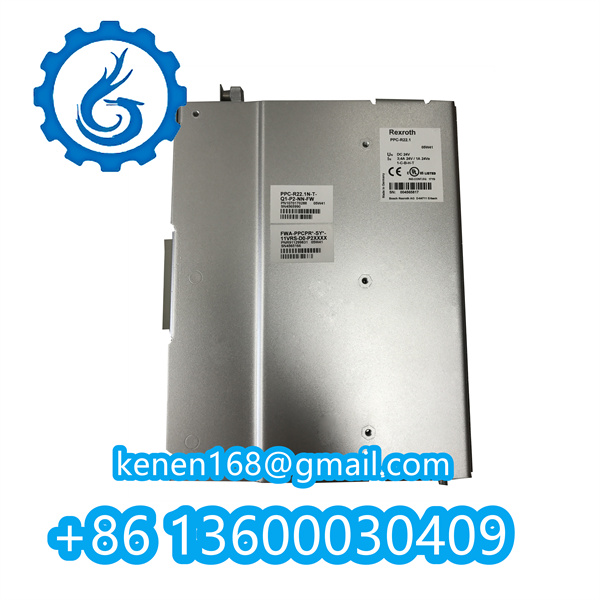
- Install the SPCIS22 module on a compatible DIN rail (refer to ABB 1SAP471600R0001 datasheet).
- Connect the 24V DC power supply (±10% tolerance) via terminal blocks X1.1-X1.2.
Functional Test Sequence
- Power-On Self-Test (POST)
- Apply power and confirm all status LEDs illuminate as follows:
- PWR (Green): Steady on
- COM (Yellow): Blinks at 1Hz during initialization.
- Apply power and confirm all status LEDs illuminate as follows:
- Communication Diagnostics
- Link the module to a control system (e.g., AC 800M) via RS485 (Terminals X2.3-X2.5).
- Send a test command (e.g.,
0x01 0x03 0x00 0x00 0x00 0x01 0x84 0x0A) and validate response frame integrity.
- Redundancy Verification (If applicable)
- Disconnect the primary communication channel and observe automatic failover to the backup link within <500ms.
- Error Simulation
- Inject a short-circuit to input channel IN1 and confirm the ERR LED activates while the system logs fault code E-412.
SPCIS22 ABB pdf
·········································································································


Reviews
Clear filtersThere are no reviews yet.