ABB BRC410 Controller Board Installation Guide
Part No.: 3BSE018105R1 (SPBRC410 variant compatible)
Pre-Installation Requirements
-
Tools & Materials
- ESD wrist strap (1MΩ resistance)
- Torque screwdriver (0.6 Nm ±10%)
- DIN rail mounting tool (for TS35 rails)
-
Environmental Conditions
- Temperature: 0°C to +55°C (derate 3%/°C above 45°C)
- Humidity: 5-95% non-condensing
- Vibration: ≤5g @ 10-500Hz (IEC 60068-2-6)

Installation Steps
Step 1: ESD Protection
procedureCopy Code
1. Connect wrist strap to grounded surface

2. Handle board only by edges (avoid contact with IC pins)
Step 2: Mechanical Mounting
| Action | Specification |
|---|---|
| Align board with DIN rail | TS35 compliant (EN 60715) |
| Secure locking clip | Audible “click” confirmation |
| Torque terminal screws | 0.6 Nm cross-tightening sequence |
Step 3: Electrical Connections
wiringCopy Code
[Power Supply]

• Terminal X1: 24V DC (18-30V range)

• Polarity: Pin1 = +V, Pin2 = 0V

• Wire gauge: 0.5-2.5mm² (AWG 20-12)
[Fieldbus]

• PROFIBUS DP: Terminate with 220Ω resistor

• Max cable length: 100m @ 1.5Mbps
Post-Installation Verification
-
Diagnostic LEDs
LED Normal State Fault Indication POWER (Green) Solid on Off = Check 24V supply COM (Yellow) Blinking 1Hz Solid = Bus communication error

-
Functional Test
test_sequenceCopy Code1. Apply power → Confirm POWER LED illumination
2. Wait 30s for boot cycle completion
3. Verify bus address via DP switch (SW1)
Critical Warnings
PROHIBITED ACTIONS
- Never hot-swap without proper bus termination1
- Avoid stacking more than 3 boards without active cooling2
- Do not exceed 250V isolation voltage between channels3
SAFETY INTERLOCKS
- Disconnect power before modifying DIP switches
- Implement emergency stop circuit per IEC 60204-1

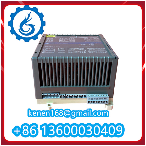
SPBRC410 ABB pdf
··········································································································

























Reviews
Clear filtersThere are no reviews yet.