


-600x600.jpg)
")


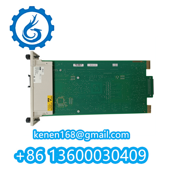
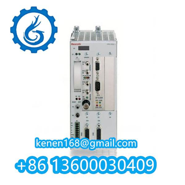
Installation Procedure for PPC-R22.1N-T-Q2-G2-NN-FW Servo Controller
1. Pre-Installation Preparation
- Verify power supply meets 24V DC (±10%) with 1.2A current capacity1.
- Prepare RMB02.2 mounting rack with cleared slot space (minimum 200mm vertical clearance)1.
- Wear ESD wrist strap when handling modules (IP20-rated components require anti-static protection)13.
2. Mechanical Installation
- Step 1: Align controller’s guide rails with RMB02.2 rack slots (83mm width tolerance ±0.5mm)1.
- Step 2: Apply vertical insertion force (max. 50N) until terminal blocks fully engage1.
- Step 3: Secure using DIN rail clips (torque specification: 0.6 N·m ±10%)1.
3. Electrical Connections
- Connect primary power via designated 24V terminals (observe polarity markings)1.
- For Q2 module:
- Wire axis control signals to DAQ03 high-speed ports (Channel A/B)1.
- For G2 module:
- Interface main encoder using LAG module’s SERCOS/DeviceNet ports15.
4. Post-Installation Verification
- Power on and check LED indicators:
- Solid green: Normal operation
- Flashing red: Refer to diagnostic手册 error codes.
- Validate communication via IndraDrive software (firmware version ≥GPP11)
·········································································································


Reviews
Clear filtersThere are no reviews yet.