


.jpg)
.jpg)
")
")
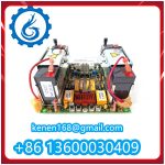
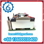
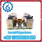
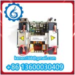

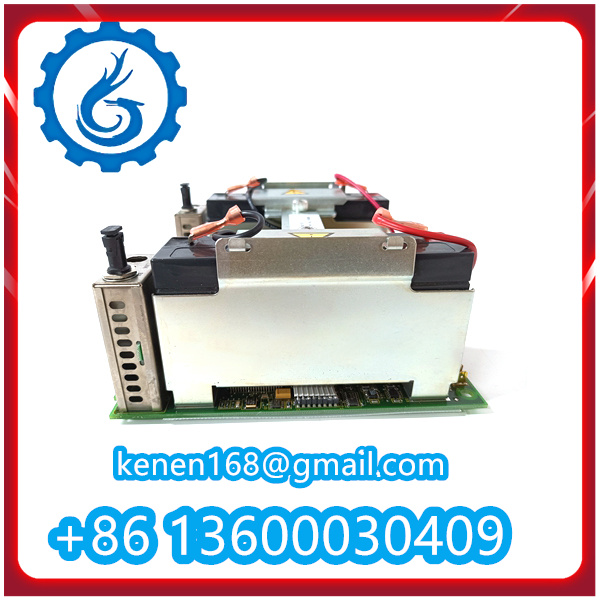
Operation Steps for NTCS04 ABB Temperature Sensor Module
The NTCS04 is a dedicated temperature sensor module for ABB industrial control systems (e.g., AC 800M DCS), designed to accurately collect, convert, and transmit temperature signals from industrial processes. Its operation steps focus on safe installation, correct configuration, and reliable signal monitoring, as detailed below:
1. Pre-Installation Preparation
- Confirm the module model NTCS04 matches the system design requirements (e.g., compatible with ABB AC 800M rack, suitable for target temperature measurement range: typically -50°C to +150°C for standard versions).
- Power off the ABB control system rack to avoid electrostatic damage or short circuits during installation.
- Prepare necessary tools and materials: torque screwdriver, wire stripper, calibrated multimeter, anti-static wristband, and ABB-approved signal cables (shielded twisted-pair cables recommended for noise reduction).
- Review the NTCS04 technical manual to confirm key parameters: power supply requirements (usually 24 VDC), signal output type (e.g., 4–20 mA analog signal), and terminal pin definitions.

2. Installation & Wiring
- Module Mounting
- Align the NTCS04 with the designated slot on the ABB AC 800M rack. Insert the module smoothly along the rack guide rails until it fully engages with the backplane connector.
- Secure the module using the provided mounting screws. Use a torque wrench to tighten screws to ABB’s specified torque (typically 0.8–1.0 N·m) to ensure stable mechanical and electrical connections.
- Wiring Connections
- Power Supply Wiring: Connect the 24 VDC power cable to the “POWER IN” terminals (labeled “+24V” and “0V” on the module). Ensure correct polarity—reverse polarity may damage internal components.
- Temperature Sensor Wiring: Connect the external temperature sensor (e.g., RTD or thermocouple, as per NTCS04 compatibility) to the “SENSOR IN” terminals. Follow the pinout diagram in the manual (e.g., 2-wire, 3-wire, or 4-wire RTD connections) to avoid signal errors.
- Signal Output Wiring: Connect the analog output cable (for transmitting temperature data to the controller) to the “SIGNAL OUT” terminals (e.g., “OUT+” and “OUT-” for 4–20 mA signals). Use shielded cables and ground the shield at one end to reduce electromagnetic interference.
- Cable Management: Organize wires using cable ties to prevent tangling. Ensure cables do not block the module’s ventilation slots or interfere with adjacent components.
3. Power-On & Configuration
- Power-On Check
- Power on the ABB control system rack in sequence: first the main rack power, then the NTCS04 module power.
- Verify the module’s LED indicators:
- Power Indicator (PWR): Steady green indicates normal 24 VDC power supply.
- Sensor Status Indicator (SENS): Steady green means the external temperature sensor is connected correctly; blinking red indicates a sensor fault (e.g., open circuit or short circuit).
- Fault Indicator (FAULT): Off = no module faults; steady red means internal module errors (e.g., power overvoltage or signal conversion failure).
- System Configuration via ABB Software
- Launch ABB Control Builder M (the configuration software for AC 800M systems) on the engineering workstation.
- Locate the NTCS04 module in the system hardware tree (identified by its slot address or module ID).
- Configure key parameters:
- Temperature Measurement Range: Set the range to match the application (e.g., 0°C–100°C for a process requiring moderate temperature monitoring).
- Signal Calibration: Use the software’s calibration tool to zero and span the 4–20 mA output signal (e.g., set 4 mA to correspond to -50°C and 20 mA to +150°C).
- Alarm Thresholds: Define high/low temperature alarm limits (e.g., alarm at >90°C or <10°C) and assign alarm output actions (e.g., trigger a system alert on the HMI).
- Save the configuration and download it to the ABB AC 800M controller. Confirm the module receives the configuration successfully (indicated by a “CONFIG OK” message on the software interface).
NTCS04 ABB PDF
········································································································


Reviews
Clear filtersThere are no reviews yet.