


.jpg "IEMMU21(1)")
-150x150.jpg)

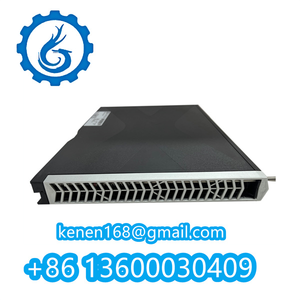
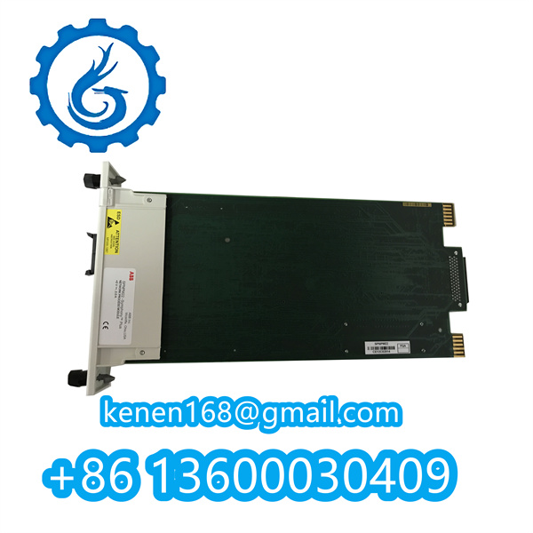
IEMMU21 Module Setup & Operation Steps
-
Physical Installation
- Mount horizontally/vertically on DIN rail with ≥100mm clearance for ventilation.
- Verify wiring to terminal blocks (A1-A8, B1-B8) per I/O schematics; tighten screws to 0.5 N·m torque.
-
Power & Communication Connection
- Connect 24VDC ±10% to
TB1(Terminals 1+: / 2-). - Link Controller Bus via RJ45 to upstream module (max. 3 cascaded units).
- Connect 24VDC ±10% to
-
Hardware Configuration
Critical: Set Node Address via DIP switch (SW1).- Example: Address “3” = Switch 1+2 ON (Binary 0011).
-
Software Integration
- In DCS/PLC engineering tool (e.g., Honeywell Experion):
textCopy Code
Add Module → Select "IEMMU21" → Enter configured Node Address → Assign I/O tags
- Validate mapping to A/B channels (e.g.,
AI_CH01 = Pressure_Transmitter01).
- In DCS/PLC engineering tool (e.g., Honeywell Experion):
-
Diagnostic Verification
- Confirm steady GREEN status LED (power) and blinking YELLOW (bus activity).
- Force analog inputs to test values (e.g., 4mA/20mA) → Check DCS readings match within ±0.1%.
-
Troubleshooting
- Red LED: Check power polarity or bus termination.
- Data skew: Verify ground wire at
TB1Terminal 3 (earth resistance <1Ω). - No signal: Validate CSV configuration file matches DIP switch addresses.
-300x300.jpg)
IEMMU21 ABB pdf
···········································································································


Reviews
Clear filtersThere are no reviews yet.