


")
")
")
")
")

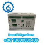
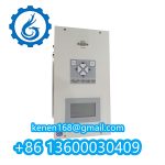

DECS-200N-C1 Excitation System Commissioning Procedure
Pre-Energization Checks
Hazard Prevention:
- Isolate generator terminals (rack-out circuit breaker)
- Ground field windings with 35mm² cable
- Verify dielectric strength (5kV AC for 1min @ bushings)
Validation Steps:
plaintextCopy Code
1. CTR/VTR Settings:

   • Field CT: 5000/5A (Verify burden ≤0.1VA)

   • PT Ratio: 13.8kV/120V
2. Insulation Resistance:

   - Control circuits: >100MΩ @ 500VDC

   - Power circuits: >500MΩ @ 2.5kVDC
3. Ground Continuity: <0.1Ω (terminal X5-17 to station grid)
Hardware Configuration
DIP Switch Settings (Front Panel):
| SW Group | Position | Function |
|---|---|---|
| SW1 | 1-ON | Auto Voltage Reg |
| 4-ON | CANbus enabled | |
| SW2 | 2-OFF | Breaker sync disable |
Terminal Wiring:
textCopy Code
X3-1  →  Generator PT (Ph-A)   [2.5mm² shielded]

X3-11 →  Field +ve             [35mm², 90°C rated]

X5-9  →  Emergency trip input  [Dry contact, 24VDC]
Power-Up Sequence
mermaidCopy Code
graph LR

A[Control Power ON] --> B[Initialize HMI]

B --> C{Self-Test Result}

C -->|PASS| D[Enable DC supply]

C -->|FAIL| E[Diagnostic Code 0xE7]

D --> F[Pre-charge resistor bypass]

F --> G[Field breaker close]
Critical Timings:
- DC link pre-charge: 3.2s ±0.5s
- HMI boot time: ≤15s
Calibration Procedure
1. Voltage Matching
plaintextCopy Code
a. Set DECS-200N to MANUAL mode
b. Adjust FVR (Field Voltage Reg) until:

   Gen Volts = Grid Volts ± 0.25%
c. Engage sync check relay (59G)
2. PID Tuning (Auto Mode)
| Parameter | Default | Optimization Range |
|---|---|---|
| Kp | 2.5 | 1.8-3.2 |
| Ti | 4.0s | 3.5-8.0s |
| Stab. Gain | 0.35 | 0.2-0.5 |
textCopy Code
*Note: Use step response test (2% ΔVref) to achieve:

  - Rise time <0.5s

  - Overshoot ≤5%*
DECS-200N-C1 BASLER ELECTRIC PDF
DECS-200N-C1 BASLER ELECTRIC l
···········································································································


Reviews
Clear filtersThere are no reviews yet.