


")
")
")


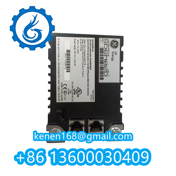
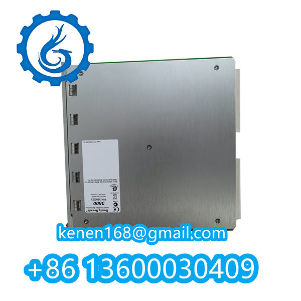
Bently Nevada 3500/33 Relay Module Operation Guide
Part Number: 3500/33-01-00-00 (4-channel configuration)
1. Safety Precautions
WARNING
- Always de-energize the rack before module insertion/removal
- Verify isolation voltage ≥250V AC between channels
- Use CAT III-rated tools for terminal adjustments

2. Installation Procedure
Step 1: Mechanical Mounting
1. Insert into 3500 rack (slot positions 3-14) 2. Secure with M4 screws (torque 0.8 Nm ±10%) 3. Maintain ≥50mm clearance from high-voltage modules
Step 2: Electrical Connections
| Terminal | Function | Specification |
|---|---|---|
| CH1-4 NO | Normally Open Contact | 8A @ 250V AC / 30V DC resistive |
| CH1-4 COM | Common Terminal | 16AWG stranded copper required |
| LED STATUS | Diagnostic Output | TTL level (5V DC max) |
3. Configuration Steps
3.1 Software Setup (Using 3500 Rack Configuration Software v5.7+)
[Relay_Configuration] Channel_Delay=0.1s ; Activation delay Fault_Latch=ENABLED ; Requires manual reset Contact_Mode=FORM_C | Options: FORM_A/B/C
3.2 Hardware DIP Switches
SW1: Channel 1-4 enable/disable SW2: Test pulse mode (ON=50ms pulse)
4. Operational Verification
Test Sequence:
- Apply 24V DC to control input
- Measure contact resistance: ≤100mΩ when energized
- Verify LED indicators:
- Green: Channel active
- Red: Fault condition

5. Maintenance Requirements
- Contact Life:
- Mechanical: 10⁸ operations
- Electrical: 10⁶ operations @ rated load
- Calibration Interval: 12 months (per API 670)
6. Compliance Data
Standards: - IEC 60204-1 (Safety of machinery) - UL 508 (Industrial control equipment) Environmental: - Operating Temp: -40°C to +85°C - Humidity: 5-95% non-condensing
Bently Nevada 3500/33 16 Channel Relay Module PDF
··········································································································


Reviews
Clear filtersThere are no reviews yet.