


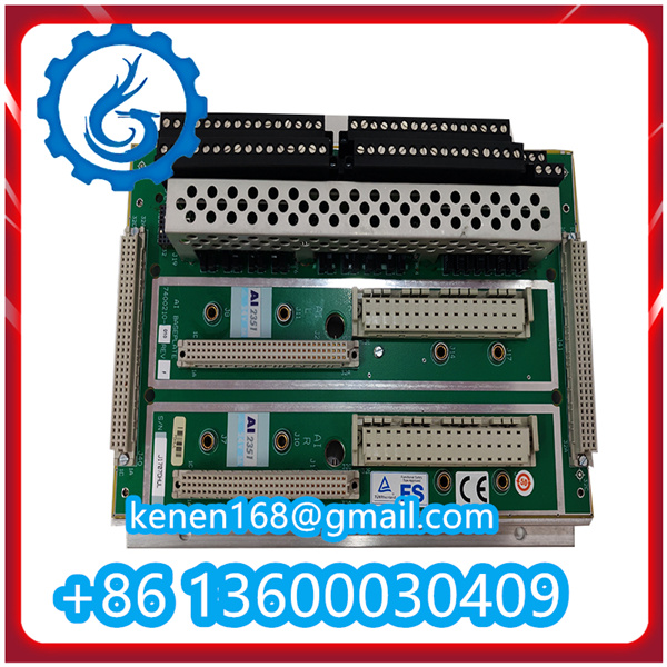
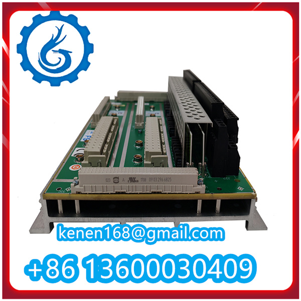
Operating Steps for TRICONEX AI2351 7400210-010 Analog Input Module
The TRICONEX AI2351 7400210-010 is a high-reliability analog input module designed for Triconex Safety Instrumented Systems (SIS) and distributed control systems (DCS), primarily used to collect and transmit analog signals (e.g., 4-20mA, ±10V) from field sensors (e.g., pressure, temperature, level sensors) to the Triconex controller. Below are the standardized operating steps, including installation, configuration, calibration, operation monitoring, and maintenance.
1. Pre-Operation Preparation & Safety Checks
Before installing or operating the module, confirm the following to ensure system safety and functionality:
- Compatibility Verification: Confirm the module model (AI2351 7400210-010) is compatible with the target Triconex controller (e.g., Triconex 3600, 3700, 4100) and the system’s backplane (TMR bus). Refer to the Triconex System Compatibility Guide for details.
- Physical Inspection: Check the module for damage (e.g., bent pins, cracked casing, loose components). Do not use the module if physical defects are found—contact TRICONEX technical support for replacement.
- Tool & Material Preparation: Gather anti-static wristbands, torque screwdrivers (with bits matching the module’s mounting screws), insulation testers, calibrated signal generators (for calibration), and the TRICONEX AI2351 Technical Manual.
- Safety Precautions:
- Ensure the Triconex system power is completely disconnected and lockout/tagout (LOTO) procedures are implemented to prevent accidental power-on.
- Wear anti-static wristbands and insulated gloves to avoid electrostatic discharge (ESD) damage or electric shock.
- Work in a clean, dry environment (humidity: 5%–95% non-condensing) to prevent moisture or dust ingress.
2. Module Installation
- Backplane Slot Identification: Locate the designated slot on the Triconex system backplane (labeled for analog input modules). Ensure the slot supports the AI2351’s TMR bus communication.
- Anti-Static Handling: Connect the anti-static wristband to a grounded surface (e.g., the system’s metal chassis) and hold the module by its edges (avoid touching pins or components).
- Module Insertion:
- Align the module’s guide rails with the backplane slot’s rails. Slide the module gently into the slot until its backplane connector makes contact with the backplane.
- Apply even pressure to the module’s front panel until a “click” is heard—this indicates the module is fully seated in the backplane.
- Secure the Module: Use a torque screwdriver to tighten the two mounting screws on the module’s front panel to the specified torque (typically 0.5–0.8 N·m). Do not over-tighten to avoid damaging the panel or backplane.
3. Wiring Connections
Follow the wiring diagram in the TRICONEX AI2351 7400210-010 Manual to connect field signals and power. Incorrect wiring may cause module damage or signal distortion:
- Power Wiring (Backplane-Powered): The AI2351 is typically powered by the system backplane (no external power cable required). Confirm the backplane provides the correct voltage (+5VDC or 24VDC, per system specifications) before wiring.
- Analog Signal Wiring:
- For 4-20mA current signals (common for field sensors): Connect the sensor’s “signal out” terminal to the AI2351’s input channel terminal (labeled “AIx+,” where “x” = channel number, e.g., AI1+, AI2+). Connect the sensor’s “ground” terminal to the module’s “AIx-” terminal.
- For voltage signals (e.g., ±10V, 0-10V): Connect the sensor’s “positive output” to “AIx+” and “negative output” to “AIx-.” Ensure the sensor’s signal range matches the module’s configured input range (to avoid overvoltage damage).
- Use shielded twisted-pair cables for signal wiring to reduce electromagnetic interference (EMI). Ground the cable shield at one end (preferably the controller side) to minimize noise.
- Isolation Check: If the module requires channel-to-channel isolation (500VDC, per AI2351 specs), ensure no shared ground exists between different input channels.
AI2351 7400210-010 TRICONEX pdf
·······································································································


Reviews
Clear filtersThere are no reviews yet.