


-150x150.jpg)

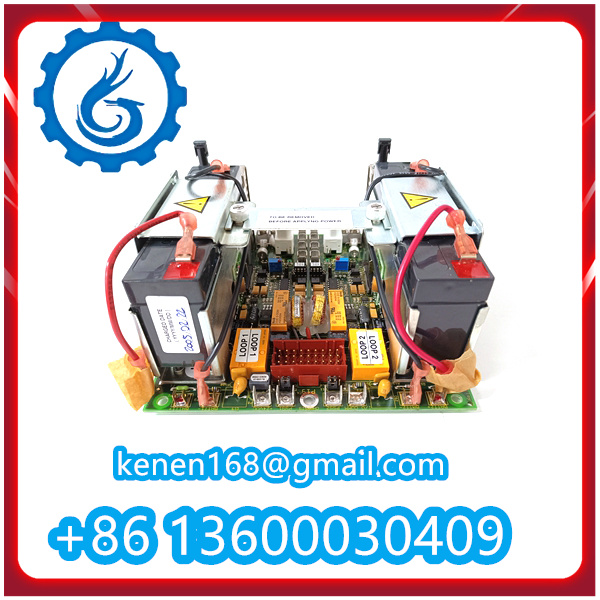
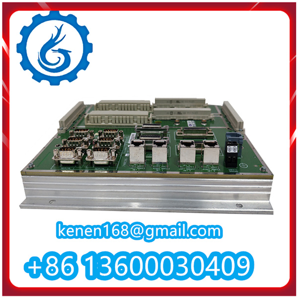
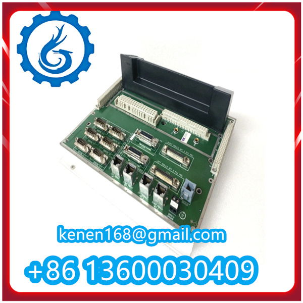
Installation Steps for A13351 Industrial Component
The A13351 is a common industrial component (typically used in automation control systems, such as sensor interfaces or auxiliary modules for process control) designed for stable integration with industrial equipment. Its installation steps prioritize safety, compatibility, and reliable electrical connections, as detailed below:
.jpg)
1. Pre-Installation Preparation
- Model & Compatibility Check
- Confirm the component model A13351 matches the system design requirements (e.g., compatible with the target industrial control cabinet/rack, and suitable for the intended application scenario such as signal conversion or device interfacing).
- Verify key technical parameters against the product manual: rated power supply (usually 24 VDC for industrial use), mounting dimensions, and terminal configuration to avoid mismatches.
- Safety & Tool Preparation
- Power off the entire industrial control system (including the target rack/cabinet) to prevent electric shock or short circuits during installation.
- Wear an anti-static wristband to protect the A13351’s internal sensitive components from electrostatic discharge (ESD).
- Prepare necessary tools: torque screwdriver (for secure mounting), wire stripper (for cable preparation), multimeter (for post-installation voltage checks), and cable ties (for wiring management).
- Environment & Space Check
- Ensure the installation location (e.g., inside the control cabinet) meets the A13351’s environmental specifications: operating temperature (typically 0–60°C), humidity (10–95% non-condensing), and no direct exposure to dust, oil, or corrosive gases.
- Confirm there is sufficient space around the A13351 for ventilation (to prevent overheating) and for accessing terminals during wiring and future maintenance.
-
2. Physical Installation of the A13351
- Rack/Cabinet Mounting
- Align the A13351 with the pre-designated mounting position on the industrial rack or control cabinet. For rail-mounted versions (common in industrial setups), slide the component onto the standard DIN rail until it clicks into place to ensure a stable base.
- If using screw mounting (for non-rail designs), place the A13351 on the mounting plate and secure it with the provided screws. Use a torque screwdriver to tighten the screws to the manufacturer’s specified torque (typically 0.8–1.2 N·m) — avoid over-tightening to prevent damage to the component’s casing or internal structure.
- Backplane Connection (If Applicable)
- If the A13351 interfaces with a system backplane (e.g., in distributed control systems), align the component’s backplane connector with the corresponding slot on the rack. Insert the A13351 smoothly into the slot until the connector is fully engaged (confirmed by a subtle “click” or resistance stop).
- Gently tug the component to verify it is securely connected to the backplane — no movement or looseness indicates a proper fit.
3. Wiring Connections
- Power Supply Wiring
- Refer to the A13351’s terminal label diagram (from the product manual) to identify the “POWER IN” terminals (usually labeled “+24V” and “0V” for DC power).
- Strip the insulation of the 24 VDC power cable (ABB-approved or industrial-grade cables recommended) to expose 5–8 mm of the conductor. Insert the positive (+24V) wire into the “+24V” terminal and the negative (0V) wire into the “0V” terminal.
- Tighten the terminal screws with a torque screwdriver (torque: 0.6–0.8 N·m) to ensure firm contact — loose connections may cause unstable power supply or overheating. Use a multimeter to pre-check the power cable (ensure no short circuit between +24V and 0V) before connection.
- Signal Wiring (Input/Output)
- Identify the “SIGNAL IN” (for receiving external signals, e.g., from sensors) and “SIGNAL OUT” (for transmitting processed signals to controllers) terminals on the A13351 via the product manual.
- For input signals (e.g., 4–20 mA analog signals from temperature/pressure sensors): Strip the sensor cable, connect the signal wires to the “SIGNAL IN” terminals (follow polarity markings: “IN+” for positive, “IN-” for negative), and tighten the terminal screws. Use shielded twisted-pair cables for signal wires and ground the shield at one end (to reduce electromagnetic interference from nearby high-voltage cables).
- For output signals (e.g., control signals to actuators): Repeat the wiring process for the “SIGNAL OUT” terminals, ensuring the cable is compatible with the receiving device’s input requirements (e.g., matching current/voltage ranges).
- Wiring Management
- Organize all power and signal cables using cable ties to prevent tangling. Route cables away from the A13351’s ventilation slots (to avoid blocking airflow) and away from high-power components (e.g., contactors, inverters) that may cause electromagnetic interference.
- Label each cable (using waterproof labels) with its function (e.g., “A13351 Power +24V,” “Sensor Signal IN”) to simplify future troubleshooting and maintenance.
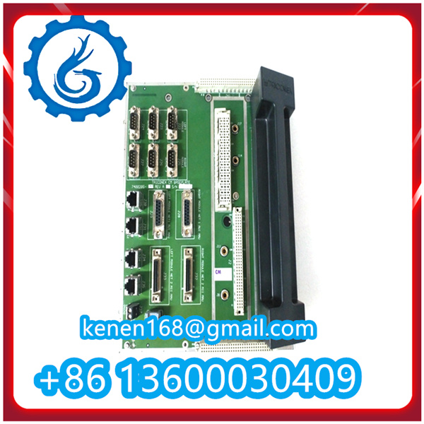
A13351 TRICONEX PDF
········································································································


Reviews
Clear filtersThere are no reviews yet.