


")
")
")
")

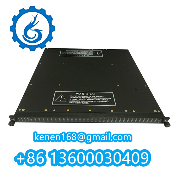
369-HI-R-M-0-P1-0-E Parameter Configuration Procedure
1. Pre-Configuration Checks
- Verify hardware version (stamped on label as “P1-0-E”)
- Ensure 24VDC power supply (±10%) is stable (measure at terminal TB1-1/2)
- Connect programming cable (USB-to-RS485 adapter recommended)

2. Communication Setup
-
Interface Selection:
- Rotary switch S1: Position “0” = Modbus RTU mode
- Baud rate: Set DIP switches SW1.1-3 to “010” = 19.2kbps
-
Device Addressing:
- Configure jumpers J1-J4 per binary encoding (Default “0001” = Modbus ID 1)

3. Core Parameter Settings
| Parameter | Register | Value Range | Factory Default |
|---|---|---|---|
| Input Scaling | 40001 | 0-65535 | 32768 |
| Output Deadband | 40012 | 0-1000 (0.1%) | 20 |
| Filter Time Constant | 40025 | 0-100 (ms) | 5 |
4. Calibration Sequence
- Zero Adjustment:
- Apply minimum input signal → Write “0” to Register 40100
- Span Adjustment:
- Apply maximum input signal → Write “10000” to Register 40101
5. Validation & Troubleshooting
- LED Indicators:
- Green: Normal operation
- Red flashing: Modbus CRC error (check termination resistor)
- Software Tools: Use vendor’s “HI-Tuner” software (v2.1.7 or later)
Safety Note: Always cycle power after parameter changes. Document settings using the QR code label.
···········································································································


Reviews
Clear filtersThere are no reviews yet.