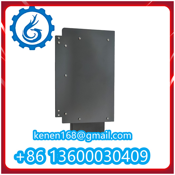
The baseplate is a unit mechanically fastened to the drawer mounting rail. All incoming and outgoing wires of the MCU (except for main currents and PTC) are connected to the baseplate. Both the Main Unit and Current Measurement Unit are plugged into the baseplate.
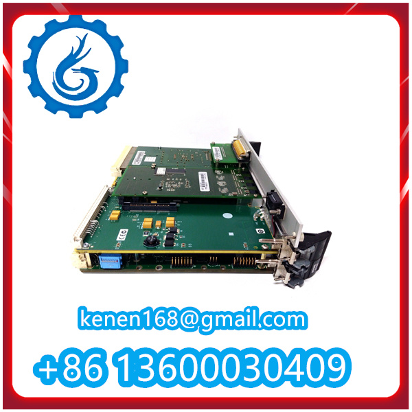
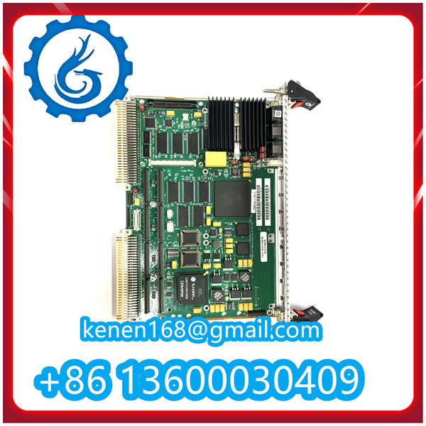
The Main Unit houses the electronics of the motor control unit. It is plugged into the baseplate.
The Current Measurement Unit contains current measurement transformers. It is plugged into the baseplate and additionally secured by the Main Unit. Two primary ranges are available: 0.1…3.2 A and 2.0…63 A.
The Voltage Unit includes three-phase voltage measurement transformers and electronics for the auxiliary power supply 2 (UAUX2). It connects to the baseplate via a flat cable and is installed alongside the MCU main unit on the drawer mounting rail.
Voltage unit detection is performed automatically through internal code signaling.
The MCU enclosure is made of polycarbonate with 10% glass fiber. The material has a UL 94 V-0 flammability rating and is halogen-free.
The material is recyclable, as indicated by the respective marking inside the enclosure parts.
The typical power consumption of the MCU is 4.7 W / 33 VDC. The maximum power consumption is 7.2 W / 33 VDC for MCU1 and 8.2 W / 33 VDC for MCU2. The power drawn by the unit depends on its connection configuration and supply voltage.
For specific applications, the maximum steady-state power consumption for both MCU1 and MCU2 can be calculated using the following values. The calculation considers the impact of supply voltage under worst-case conditions (33 VDC supply).
Some connections are designed for both internal and external drawer use, effectively creating an internal cross-connection between connectors X13 and X14. Practically, the difference between the connectors lies in their disturbance filtering, with X13 featuring stronger filtering than X14.
Due to this design, users must not simultaneously use or connect both connectors for a single input, nor cross-connect common wires between connectors.
MCU1 has 12 digital inputs, while MCU2 has 17, all of the 10 mA / 24 VDC type. A digital input is activated when connected to its corresponding common terminal.
The polarity of the inputs can be parameterized as either Normally Open (NO) or Normally Closed (NC). With polarity selection, the active condition for each input can be set individually. For default polarities and additional information, refer to the appendix “MCU1 and MCU2 DIGITAL INPUT CONFIGURATION”.
For example, the Local input on unit MCU1A01C01-4 is activated when terminal X13:16 is connected through a switch to terminal X13:25 on the same connector. When the input is parameterized as normally open, the device operates in local control mode.
Digital inputs are located on connectors X13 and X14. The appropriate connector is selected based on whether the input wiring originates from inside or outside the drawer.

1TGB302003R0003 ABB PDF
060815_1TGC901022M0201_MCU Users Guide V3.0d
·······································································································
Our advantages:
1. The brand new product comes with a one-year
comprehensive warranty.
2. All products undergo strict quality inspections.
3. Contact us and our team will provide competitive
quotes and procurement plans.


Reviews
Clear filtersThere are no reviews yet.