


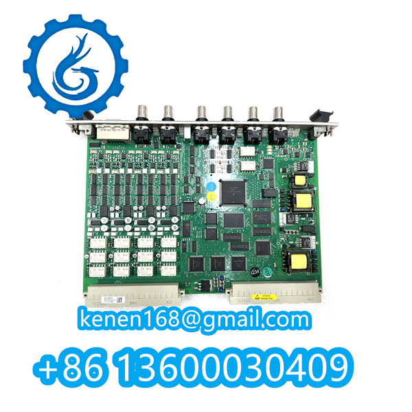
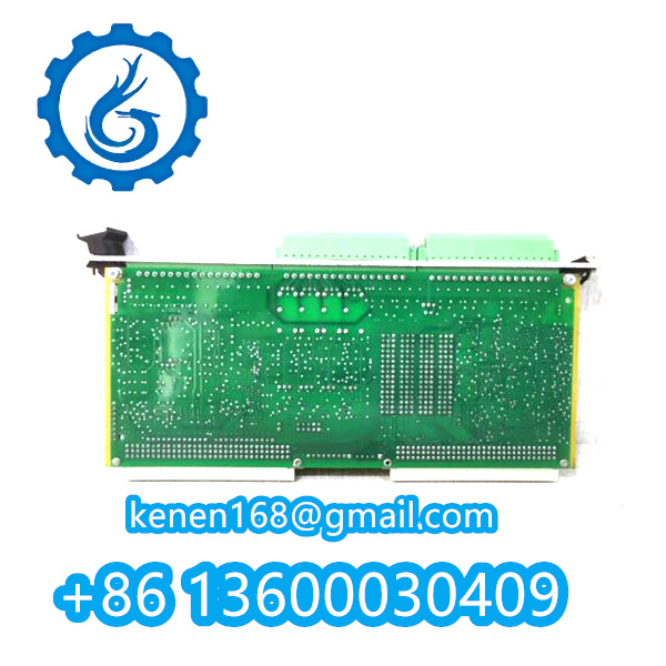


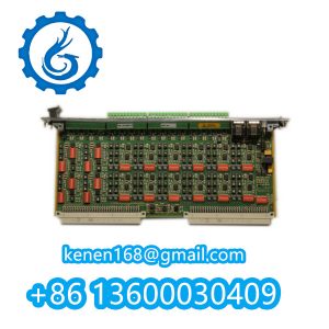
The VMF-IOC16T (200-565-101-013 / 200-565-000-013) PCB Circuit Board Operational Steps
Key Procedures
-
Pre-Installation Checks
- Verify P/N labels match (200-565-101-013 for standard I/O, 200-565-000-013 for redundant configurations).
- Inspect PCB for physical damage (e.g., cracked traces or burnt components).
-
Power & Grounding
- Connect 24V DC ±5% to terminals
PS+/PS-(redundant power inputs if applicable). - Ensure chassis ground resistance ≤0.1Ω via dedicated grounding screw.
- Connect 24V DC ±5% to terminals
-
I/O Wiring
- Analog Inputs (AI1-AI8): Use shielded twisted pairs (e.g., Belden 8761) for 4-20mA/1-5V signals.
- Digital Outputs (DO1-DO4): Max load 2A @ 30V DC per channel.
- Isolation: Maintain 500V isolation between channels (CAT II).
-
Configuration
- Dip-switch settings (SW1-SW4):
- SW1.1 ON: Enable Modbus RTU (address set via SW2-SW4 binary coding).
- SW1.2 ON: Activate fail-safe mode for DOs.
- Calibrate AI channels via VM600 QuickCal software (offset ±0.1% FS adjustable).
- Dip-switch settings (SW1-SW4):
-
Diagnostics
- LED Indicators:
- Green (PWR): Power OK
- Red (ERR): Fault (check VM600 event log)
- Measure test points (TP1-TP3) with multimeter:
- TP1: +5V ref (±0.5%)
- TP2: Ground integrity (≤10mV noise)
- LED Indicators:
vmf-IOC16T 200-565-101-013 200-565-000-013 PDF
vmf-IOC16T 200-565-101-013 200-565-000-013
···········································································································


Reviews
Clear filtersThere are no reviews yet.