


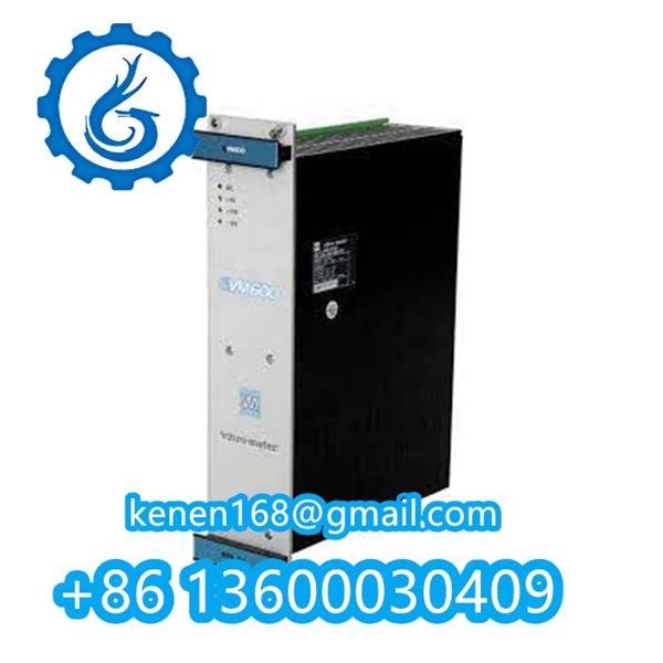


Vibro-Meter VMF-CPUM 200-595-046-114 Quick Setup Guide
1. Hardware Installation
- Mounting: Secure the module in a compatible VM600 rack or DIN rail enclosure.
- Wiring:
- Connect 24V DC power to terminals
A1 (+)andA2 (-). - Link sensors (accelerometers, proximity probes) to dedicated input channels (e.g.,
CH1-CH8). - Integrate with control systems via Ethernet (RJ45) or RS485 (terminals
COM1/COM2).
- Connect 24V DC power to terminals
2. Initial Power-Up Sequence
- Apply power; verify PWR LED illuminates green.
- Wait for RUN LED to flash (module initializing).
- Confirm FAULT LED remains off (no critical errors).
3. Software Configuration
Requires VM600 Workstation Suite installed on PC:
- Step 1: Connect PC to module via Ethernet switch.
- Step 2: Launch VM600 Configurator, detect module using factory IP (
192.168.1.100). - Step 3: Configure monitoring parameters:
plaintextCopy Code
- Sensor Type: IEPE/Proximity (select per channel)

- Measurement: Vibration (ppm/µm), Speed (RPM), Temperature (°C)

- Alarms: Set thresholds (e.g., Warning: 100µm, Danger: 150µm)
- Step 4: Save configuration to module flash memory.
4. Runtime Operation
- Real-time Monitoring:
- View live data via VM600 Dashboard (trends, waveforms).
- Check STATUS LEDs:
- GREEN = Normal operation
- YELLOW = Warning threshold breached
- RED = Danger threshold breached → Triggers relay outputs
- Relay Control: Assign shutdown/alarm logic to relay outputs (
OUT1-OUT4).
5. Diagnostics & Troubleshooting
| LED State | Meaning | Action |
|---|---|---|
| PWR off | No power | Check wiring/voltage |
| RUN flashing red | Firmware error | Reflash firmware via USB port |
| FAULT steady red | Hardware failure | Replace module |
···········································································································


Reviews
Clear filtersThere are no reviews yet.