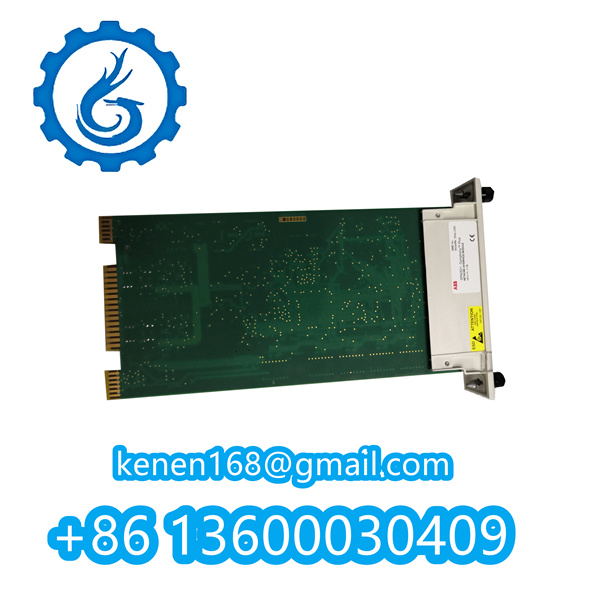
Operating Procedures for V4561983-0100 ALSTOM Controller
1. Pre-Installation Preparation
- Confirm the controller model V4561983-0100 matches the design specifications of the Alstom control system (e.g., turbine control or power plant automation system).
- Power off the entire control system and wear an anti-static wristband to prevent electrostatic damage to internal components.
- Prepare tools (e.g., torque screwdriver, wire stripper) and check that auxiliary accessories (e.g., connection cables, terminal blocks) are intact and compatible.
2. Installation & Wiring
- Align the controller with the designated slot on the Alstom system rack, insert it smoothly until it is fully seated, and secure it with mounting screws (follow the torque requirement specified in the manual, typically 0.8–1.2 N·m).
- Connect the power cable: According to the technical datasheet, connect the rated power supply (usually 24 VDC or 110 VAC) to the power terminal of the controller; ensure correct polarity to avoid reverse connection.
- Connect signal cables:
- Connect input signals (e.g., sensor signals, feedback signals) to the “INPUT” terminals.
- Connect output signals (e.g., control signals for actuators) to the “OUTPUT” terminals.
- Tighten terminal screws to prevent loose connections; use cable ties to organize wiring and keep it away from high-voltage cables or electromagnetic interference sources.
3. Power-On & Configuration
- Power on the control system in sequence (first the main power, then the controller power). Check the LED indicators on the controller:
- A steady green “PWR” light indicates normal power supply.
- No red “FAULT” light means no hardware errors; if the “FAULT” light is on, power off immediately and check wiring or component integrity.
- Access the Alstom configuration software (e.g., Alstom Ovation Configuration Studio) via the HMI or engineering workstation. Locate the controller by its address (pre-assigned during system design) and load the pre-configured control program (e.g., logic for turbine speed regulation or load control).
- Verify configuration parameters: Check key settings (e.g., input/output signal ranges, alarm thresholds, communication protocols like Modbus or Profinet) to ensure they match the on-site requirements. Save and activate the configuration.
4. Startup & Operation
- Switch the controller to “RUN” mode (via the physical switch on the controller or the software interface).
- Monitor real-time data on the HMI: Track input signal values (e.g., temperature, pressure) and output status (e.g., actuator position) to confirm the controller correctly receives and processes signals.
- Perform a test run: Issue a manual control command (e.g., “start” or “adjust” signal) via the HMI to check if the controller drives external devices (e.g., valves, motors) as expected. Record response time and action accuracy to ensure compliance with operational standards.
·········································································································
Reviews
Clear filtersThere are no reviews yet.