


.jpg)


Problem Analysis
- User Requirement: Rewrite the operational procedures for DEIF PSM-1 Power Supply Module in English.
- Key Points:
- Technical Accuracy: Ensure precise translation of power supply module operations (e.g., startup, diagnostics).
- Structural Clarity: Present steps hierarchically (e.g., numbered lists for sequential actions).
- Terminology Consistency: Adhere to industrial standards (e.g., “DC bus voltage” over colloquial terms).
- Contextual Links:
- Align with DEIF’s documentation style2 and Rittal PSM module’s safety protocols1.
- Highlight compatibility with ATV series inverters if applicable2.
- Caution Notes:
- Include safety warnings (e.g., isolation procedures).
- Reference LED indicators for fault diagnosis1.
Operational Procedures (English Version)
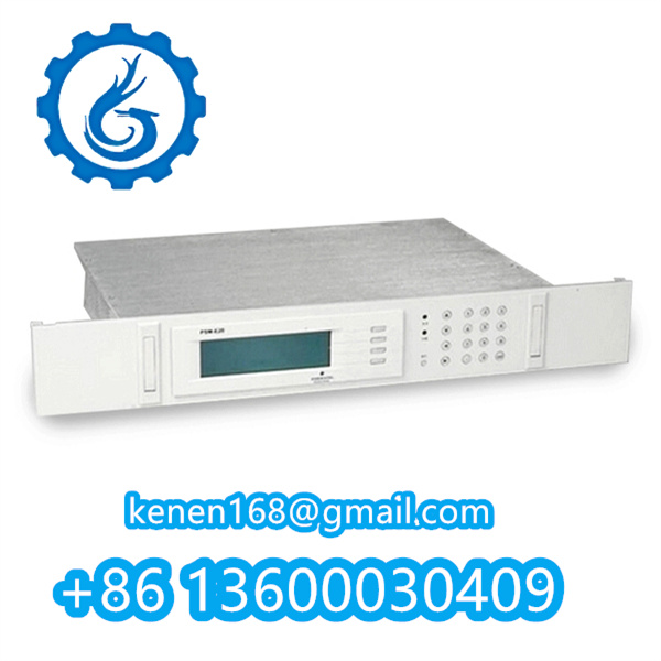
DEIF PSM-1 Power Supply Module – Startup & Maintenance Guide
1. Pre-Operation Checks
- Verify input voltage: 24V DC (±5%), max load 10A2.
- Inspect terminals for corrosion or loose connections.
- Confirm ambient temperature: -25°C to +70°C (derate above 50°C)1.
2. Power-On Sequence
- Step 1: Engage main circuit breaker (rated ≥15A).
- Step 2: Monitor STATUS LED:
- Green steady: Normal operation.
- Red flashing: Overcurrent/overvoltage fault1.
- Step 3: Check output voltage (12V/24V DC) with multimeter.
3. Integration with Control Systems
- For ATV930/950 inverters: Connect via shielded cables (max length: 3m)2.
- Grounding: Use ≤10Ω resistance path to chassis ground.
4. Maintenance & Troubleshooting
- Monthly: Clean air vents with dry compressed air (≤0.3MPa).
- Error Codes:
- E01: Input undervoltage → Verify supply stability.
- E02: Overtemperature → Ensure 50mm clearance for ventilation
PSM-1 DEIF PDF
delomatic-3-analogue-output-module-4921240064-uk
·········································································································


Reviews
Clear filtersThere are no reviews yet.