


")

")
")


technical guide for the Motorola MVME5500 Single-Board Computer
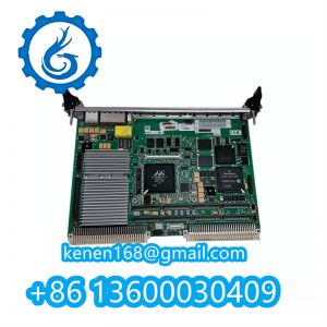
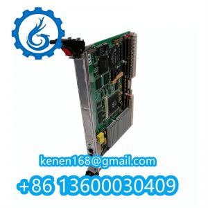
Motorola MVME5500 Series VME Processor Board
Model: MVME5500-0163 (733 MHz MPC7455)
Form Factor: 6U VME (233 × 160 mm)
Hardware Specifications
| Component | Configuration |
|---|---|
| CPU | PowerPC G4 MPU (MPC7455/7457) @ 733 MHz–1 GHz |
| Memory | 512 MB DDR SDRAM (expandable to 2 GB) |
| L2 Cache | 256 KB integrated |
| Interfaces | • Dual Gigabit Ethernet (RJ45) |
| • Dual PMC slots (P1/P2) | |
| • RS-232/422 serial (DB9) | |
| • SCSI-2 (68-pin VHDCI) | |
| • USB 1.1 (Type A) | |
| Bus Architecture | VME64x (Master/Slave) + PCI-X @ 133 MHz |
Installation Procedure
Step 1: Mechanical Mounting
textCopy Code
1. Verify backplane compatibility: J1/J2 pinout per VME64x (DIN 41612)
2. Insert into VME crate slot:

   • Align ejector handles (P0 connector first)

   • Torque retention screws: 0.6 Nm ±0.1 Nm
3. Grounding: Connect chassis to VME P0 pin A1 (≤0.1Ω impedance)
Step 2: Power Requirements
| Rail | Voltage | Current (Max) | Tolerance |
|---|---|---|---|
| +5V | 5.1 VDC | 15A | ±5% |
| +3.3V | 3.3 VDC | 12A | ±5% |
| +12V | 12.0 VDC | 1.5A | ±10% |
| -12V | -12.0 VDC | 0.3A | ±10% |
Note: Use 18 AWG minimum for power cabling. Derate 2% per 500m ASL.
Configuration & Initialization
DIP Switch Settings (SW1)
textCopy Code
SW1.1: FLASH Write Protect (ON=Protected)

SW1
2: Boot Source (ON=PMC, OFF=VME)
SW1.3: Console Redirection (ON=Serial)
SW1.4: NVRAM Clear (ON=Reset config)
Firmware Initialization
bashCopy Code
# Access Debugger via serial (115200/8/N/1):

MVME5500>> setenv auto-boot? false

MVME5500>> init-memory

MVME5500>> boot -f "vxWorks.bin"
Critical Operating Constraints
Thermal Management
- Ambient Temp: 0°C to +55°C (forced airflow required)
- Airflow: ≥300 LFM at heatsink (ΔT <10°C above ambient)
- Heat Dissipation: 45W max (with dual PMC modules)
EMC Precautions
- Install ferrites on I/O cables: TDK ZCAT2035-0930A
- Maintain ≥50 mm clearance from RF sources
- Shield unused PMC connectors (P/N 07-00321)
Diagnostic Indicators
| LED | State | Status |
|---|---|---|
| PWR (Green) | Solid | Power OK |
| CPU (Yellow) | Blinking (1Hz) | Processor active |
| FAULT (Red) | Flashing | SDRAM ECC error |
| ETH1/2 (Amber) | On | Link established |
Software Support
plaintextCopy Code
OS Compatibility:

• VxWorks 5.5.1 (BSP 2.3)

• Linux 2.6 (Denx ELDK)

• QNX 6.5
Driver Requirements:

- Wind River PPCdiag 4.7+ for diagnostics

- SCSI: Adaptec AIC-7899W driver v2.15

- PCI-X: Enable M66EN jumper (J12) for 133 MHz
Maintenance & Troubleshooting
Voltage Test Points
| TP | Signal | Nominal Value | Tolerance |
|---|---|---|---|
| TP1 | VCC_CORE | 1.3 VDC | ±3% |
| TP7 | DDR_VREF | 1.25 VDC | ±1% |
Common Faults
- No Boot: Check VME P2 pin D08 (SYSRESET#) ≥3.3V
- PCI-X Fail: Verify J12 jumper for 64-bit mode
- Memory Error: Reseat DIMMs (30N insertion force)
MVME5500 MOTOROLA PDF
··········································································································


Reviews
Clear filtersThere are no reviews yet.