


Installation Steps for 369-HI-R-0-0-0-0-E GE
1.Pre-Installation Preparation
1.1 Check Installation Environment
Before starting the installation, first confirm that the installation environment meets the requirements of the 369-HI-R-0-0-0-0-E GE device. Specifically, check the following items:
- Ambient temperature: Ensure the ambient temperature is within the range specified in the device manual (generally -20°C to 60°C). Avoid installing the device in an environment with extreme high or low temperatures, direct sunlight, or strong heat radiation sources.
- Humidity: The relative humidity should be between 5% and 95% without condensation. Prevent the device from being installed in a damp environment to avoid short circuits or component damage caused by moisture.
- Vibration and shock: The installation location should be free from excessive vibration and shock. If the environment has vibration, necessary shock absorption measures (such as installing shock-absorbing pads) should be taken to ensure the stable operation of the device.
- Space requirements: Confirm that there is sufficient installation space around the device to facilitate heat dissipation, wiring, and subsequent maintenance. The distance from the device to surrounding obstacles should not be less than the minimum value specified in the manual.
1.2 Verify Equipment and Accessories
Carefully check whether the 369-HI-R-0-0-0-0-E GE device and its supporting accessories are complete and intact, and there is no damage during transportation. The specific verification items include:
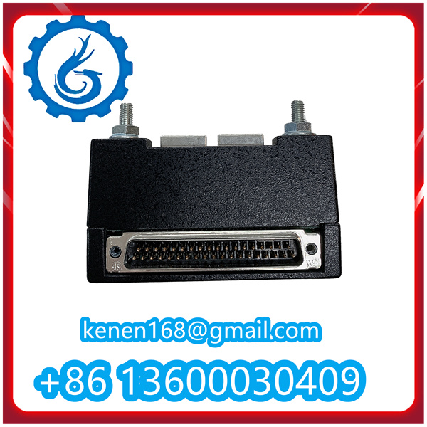
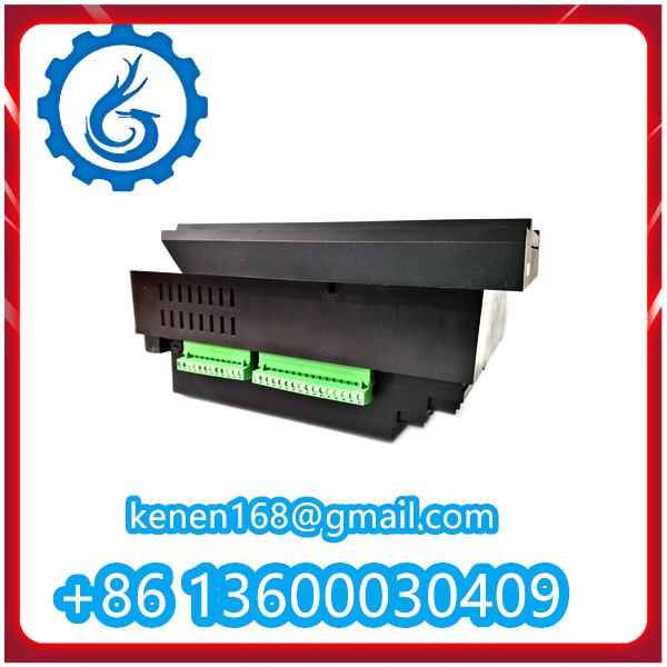
- Main device: Check the appearance of the 369-HI-R-0-0-0-0-E GE main unit for scratches, cracks, or deformation. Confirm that the indicator lights, buttons, and interfaces on the device are intact.
- Accessories: Check whether the supporting mounting brackets, screws, washers, wiring terminals, and other accessories are complete and consistent with the list in the manual. If any accessories are missing or damaged, contact the supplier in time for replacement.
- Documentation: Confirm that the product manual, installation guide, certificate of conformity, and other documents are complete. These documents will provide important guidance for the subsequent installation and commissioning work.

1.3 Prepare Installation Tools
Prepare the necessary tools for installation in advance to ensure the smooth progress of the installation work. The required tools mainly include:
- Mechanical tools: Screwdrivers (cross-head and flat-head), wrenches (open-end wrench, socket wrench), pliers, a level, a tape measure, etc.
- Electrical tools: Multimeter (for testing voltage, current, resistance), wire strippers, crimping tools, insulation tape, etc.
- Safety tools: Insulated gloves, safety glasses, a helmet (if working at height), etc. Ensure that all tools are in good condition and meet the safety requirements.
2.Device Mounting
2.1Determine Mounting Position
According to the on-site layout and the requirements of the device manual, determine the specific mounting position of the 369-HI-R-0-0-0-0-E GE device. The following principles should be followed when determining the position:
- The position should be convenient for wiring and subsequent maintenance operations, and there should be no obstacles affecting the operation.
- Avoid installing the device near strong electromagnetic interference sources (such as motors, transformers, etc.) to prevent electromagnetic interference from affecting the normal operation of the device.
- Ensure that the mounting surface is flat and firm, and can bear the weight of the device. If mounting on a wall or cabinet, confirm that the mounting surface has sufficient load-bearing capacity.
2.2 Install Mounting Bracket
If the device needs to be mounted on a wall or cabinet, first install the mounting bracket according to the instructions in the manual. The specific steps are as follows:
1.Place the mounting bracket on the determined mounting position, adjust the position to make it level (use a level for calibration).
2.Mark the positions of the mounting holes on the mounting surface through the holes on the bracket.
3.Drill holes at the marked positions with a drill (the size of the drill bit should match the size of the expansion screws used).
4.Insert the expansion screws into the drilled holes, and fix the mounting bracket on the mounting surface by tightening the nuts with a wrench. Ensure that the bracket is firmly fixed without looseness.
2.3 Fix the Device to the Bracket
After the mounting bracket is installed firmly, place the 369-HI-R-0-0-0-0-E GE device on the bracket, align the mounting holes on the device with the holes on the bracket, and then use the matching screws to fix the device. The specific steps are:
Lift the device carefully (pay attention to the weight of the device to avoid injury) and place it on the mounting bracket, ensuring that the mounting holes are aligned.
Insert the screws into the aligned holes, and tighten the screws evenly with a screwdriver. Do not over-tighten the screws to avoid damaging the device shell or threads.
After fixing, check whether the device is stable, and there is no shaking or looseness. If there is looseness, re-tighten the screws.

3.Wiring Connection
Wiring Preparation
Before wiring, make full preparations to ensure the safety and correctness of the wiring. The specific preparations include:
- Cut off the power supply of the relevant circuit to avoid electric shock accidents during wiring. Hang a “No Power On” sign at the power switch to remind others not to turn on the power at will.
- According to the wiring diagram in the device manual, confirm the type, specification, and color of the wires to be used. Ensure that the wire cross-sectional area meets the current-carrying requirements of the device.
- Use wire strippers to strip the insulation layer of the wire ends (the length of the stripped insulation layer should match the depth of the wiring terminal), and ensure that the wire core is not damaged.


Reviews
Clear filtersThere are no reviews yet.