


- Product Positioning & Core Purpose
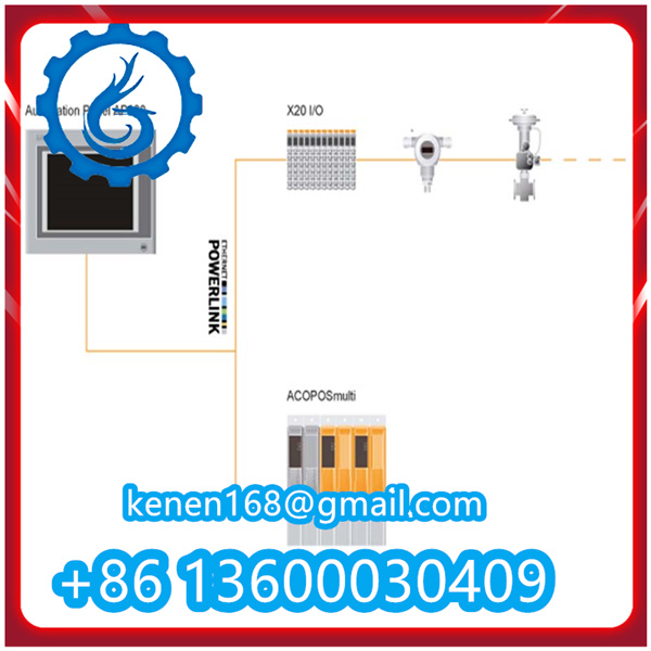
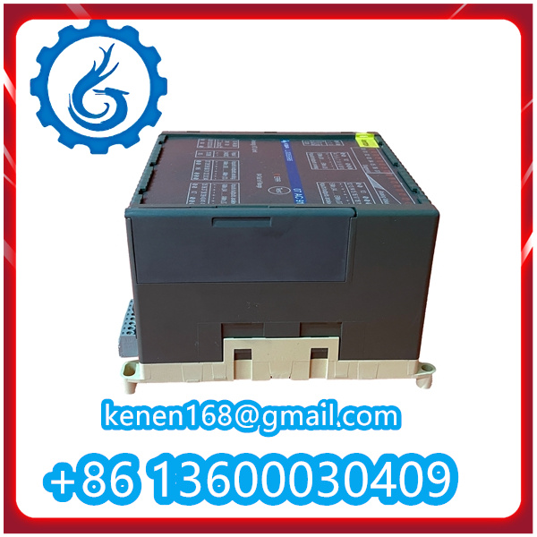
The 07AC91 serves as a critical signal conversion and control interface module in industrial automation systems. Its primary function is to bridge the gap between field devices (sensors, transmitters) and upper-level control systems (PLC/DCS/HMI), enabling reliable signal transmission, logic execution, and actuation control while adapting to harsh industrial environments.
- Fundamental Working Principle Framework
The module operates based on the “signal acquisition → processing → control output → feedback monitoring” closed-loop mechanism, leveraging industrial-grade circuit design and protocol compatibility to ensure stable performance. Key working stages are detailed as follows:

2.1 Power Supply & Initialization
The module receives rated power (typically DC 24V ±10%, compliant with ABB’s standard power specifications) via dedicated power terminals (L/V+ and N/GND).
Upon power-on, an internal microcontroller initiates a self-test sequence: verifying circuit integrity, checking communication port functionality, and initializing default parameters (e.g., signal input/output type, communication baud rate).
A solid “RUN” LED indicator confirms successful initialization, indicating the module is ready for operation.
2.2 Input Signal Acquisition & Conditioning
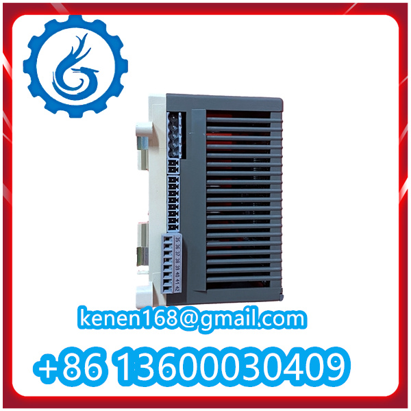
Signal Reception: The 07AC91 collects signals from field devices through its input channels (typically 8-channel analog input: 4~20mA/0~10V, or digital input: dry contact/NPN/PNP). Analog signals originate from sensors (temperature, pressure, flow), while digital signals come from limit switches, buttons, or status sensors.
Signal Conditioning: Raw input signals undergo precision processing to eliminate interference and ensure accuracy:
Analog signals: Amplified via operational amplifiers, filtered to remove electromagnetic noise (compliant with IEC 61000-6-4 EMC standards), and converted to digital data by a 16-bit ADC (Analog-to-Digital Converter) with ±0.1% FS conversion accuracy.
Digital signals: Debounced (eliminating contact bounce noise) and level-shifted to match the module’s internal logic voltage (3.3V/5V), ensuring reliable logic recognition.
2.3 Control Logic Execution & Communication Interaction
Data Transmission to Upper System: The conditioned signals are transmitted to the connected PLC/DCS via standard industrial communication protocols (e.g., Modbus RTU, Profibus DP) through Ethernet (RJ45) or RS485 ports. The module acts as a slave device, responding to read/write commands from the master controller.
Logic Execution: The 07AC91 supports two operational modes based on system configuration:
Passive Transmission Mode: Directly forwards processed input signals to the upper system without local logic intervention, relying on the PLC/DCS for control decision-making.
Local Logic Mode: Executes pre-configured logic (e.g., interlocking, threshold comparison) via its built-in programmable microcontroller. For example, triggering an output signal if an analog input exceeds a set threshold, enabling rapid local control without upper system latency.
2.4 Output Actuation & Device Control
Upon receiving control commands from the upper system or local logic, the module drives its output channels (typically 4-channel analog output: 4~20mA, or digital output: relay/transistor):
Analog Output: A 12-bit DAC (Digital-to-Analog Converter) converts digital control signals back to standardized analog signals, regulating actuators such as control valves, variable-frequency drives (VFDs), or proportional regulators.
Digital Output: Activates relay/transistor switches to control the on/off status of field devices (e.g., pumps, motors, solenoid valves). Relay outputs handle high-voltage/current loads (up to AC 250V/5A), while transistor outputs suit low-power, high-frequency switching scenarios.


Reviews
Clear filtersThere are no reviews yet.