Introduction to the Overload Protection Mechanism of VCIB-06
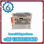
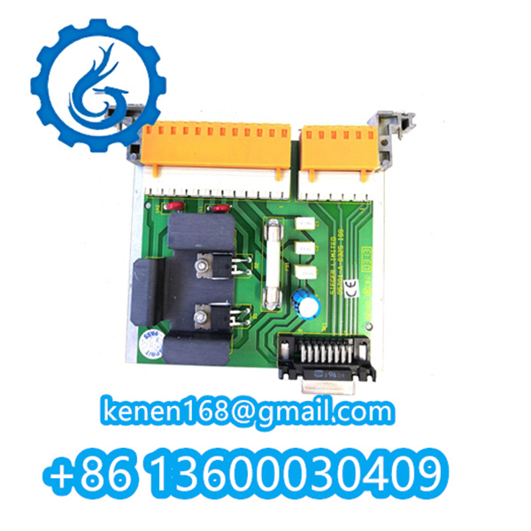
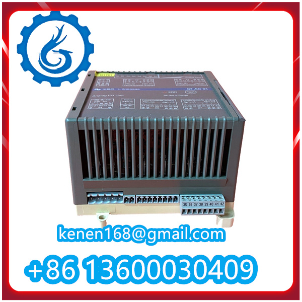
As a member of Reliance Electric’s Vectrive series AC servo vector drives, the VCIB-06 is equipped with a multi-stage overload protection mechanism. This mechanism is designed to prevent damage to the drive itself, the connected servo motor, and associated equipment caused by excessive current or load during operation. Below is a detailed breakdown of its core functional logic and implementation steps:
1. Real-Time Current Sensing: The First Detection Barrier
The VCIB-06 integrates high-precision current sensors (typically Hall-effect sensors or current transformers) in its power circuit. These sensors continuously monitor the phase current of the connected servo motor (including both steady-state operating current and inrush current during startup).
- The sensors convert the detected analog current signals into digital signals via an internal analog-to-digital converter (ADC), then transmit the real-time current data to the drive’s central control unit (MCU or dedicated vector control chip) at a high sampling frequency (usually ≥10kHz).
- This real-time monitoring ensures that even transient current spikes (e.g., those caused by sudden load increases) are not missed, laying the foundation for timely overload identification.
2. Threshold Comparison & Time-Delay Judgment: Avoiding False Triggers
The VCIB-06’s control unit pre-stores two key overload-related parameters (configurable via the drive’s parameter setting interface or supporting software):
- Rated Overload Current Threshold: Typically set to 1.5–2.5 times the drive’s rated output current (the exact value depends on the VCIB-06’s model specifications and motor matching requirements). For example, if the drive’s rated current is 6A, the overload threshold might be set to 9A (1.5x) for continuous operation or 12A (2x) for short-term peaks.
- Overload Time-Delay Setting: A time window (e.g., 0.5–10 seconds) that prevents false protection triggers from short-duration current surges (e.g., momentary motor jamming or startup inrush current).
The control unit compares the real-time current data with the preset overload threshold:
- If the detected current exceeds the threshold but lasts less than the time delay, the drive judges it as a transient disturbance and does not activate protection.
- If the overcurrent state persists beyond the time delay, the drive confirms an “overload fault” to avoid prolonged overheating of the motor windings or drive power components.
3. Protective Actions: Multi-Level Safety Responses
Once an overload fault is confirmed, the VCIB-06 executes a series of graded protective actions to minimize risk:
- Immediate Output Shutdown: The drive’s power switching components (IGBTs) are rapidly turned off to cut off the power supply to the motor, stopping the motor from running and preventing further current buildup.
- Fault Signaling:
- The drive’s front-panel indicator (e.g., a red “FAULT” LED) flashes or stays on to visually alert operators to the overload issue.
- If the VCIB-06 is connected to a PLC or HMI via communication ports (e.g., RS-485, Modbus), it sends an overload fault code (e.g., “OL1” for motor overload) to the upper-level control system for remote monitoring and troubleshooting.
- Fault Memory: The drive stores the overload fault information (including fault time, current value at fault, and operating status) in its internal non-volatile memory (NVM). This allows maintenance personnel to retrieve historical fault data later for root cause analysis (e.g., distinguishing between persistent load overload and occasional mechanical jamming).
4. Reset Mechanism: Restoring Operation Safely
After the overload cause is eliminated (e.g., reducing the motor load, resolving mechanical jamming), the VCIB-06 supports two reset modes to resume operation:
- Manual Reset: Operators press the dedicated “RESET” button on the drive’s front panel or send a manual reset command via the upper-level control system. This mode is suitable for critical applications where human confirmation of fault resolution is required.
- Automatic Reset (Optional): If enabled via parameter settings, the drive automatically attempts to reset the fault after a preset delay (e.g., 30 seconds) and checks if the current returns to the normal range. If the overload state persists, the drive re-activates protection to prevent repeated fault cycles.
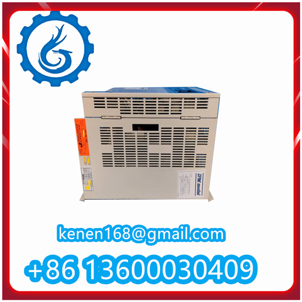
VCIB-06 RELIANCE INSPECTOR NEW pdf
·······································································································

















Reviews
Clear filtersThere are no reviews yet.