


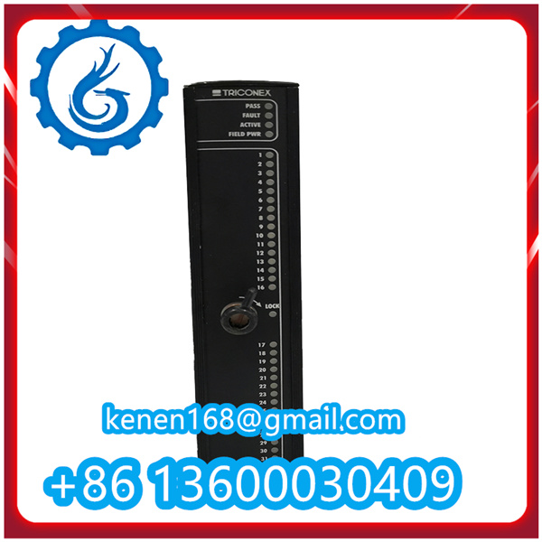


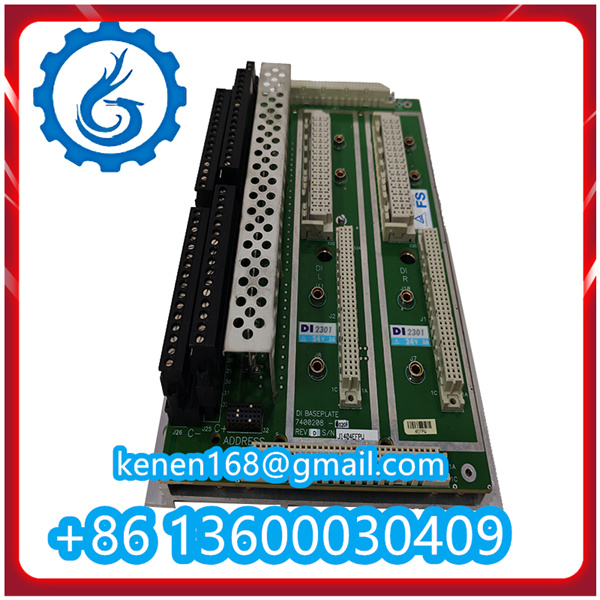
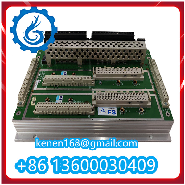
The TRICONEX A12351 (7400210-010) is a safety-rated I/O module (inferred as analog input/output module based on TRICONEX 7400-series naming logic) designed for integration with TRICONEX Safety Instrumented Systems (SIS). Proper installation is critical to ensure compliance with safety standards (e.g., SIL 2/3 per IEC 61508) and reliable operation. Below are the step-by-step installation guidelines, aligned with TRICONEX’s official safety procedures and industrial best practices:
1. Pre-Installation Preparation
Before starting installation, confirm the following to avoid safety hazards and installation errors:
- Verify Module Compatibility: Check that the A12351 (7400210-010) is compatible with your TRICONEX SIS chassis (e.g., Tricon, Trident) and controller firmware version (refer to TRICONEX’s System Compatibility Matrix).
- Gather Tools & Materials: Prepare insulated screwdrivers (Phillips #2), torque wrench (set to 0.5–0.8 N·m), wire strippers (for 16–24 AWG wires), crimping tool (for terminal lugs), anti-static wristband, and the module’s official Wiring Diagram (included in the product package or downloadable from TRICONEX’s website).
- Execute LOTO Procedures: Lock out/tag out (LOTO) the SIS chassis power supply and related field equipment to prevent electrical shock or accidental system activation during installation.
- Inspect Module & Chassis:
- Check the A12351 module for physical damage (e.g., bent pins, cracked housing, loose components) — do not install damaged modules.
- Inspect the TRICONEX SIS chassis backplane: Ensure no pins are bent, corroded, or contaminated with dust. Clean the backplane with a dry, lint-free cloth if needed.
2. Mount the A12351 Module to the SIS Chassis
Follow these steps to securely install the module into the chassis:
- Put On Anti-Static Protection: Wear an anti-static wristband (connected to the chassis ground terminal) to prevent electrostatic discharge (ESD) damage to the module’s internal components.
- Align the Module with Chassis Slots: Identify the correct slot in the SIS chassis for the A12351 (refer to your system’s Slot Assignment Plan — I/O modules typically occupy slots adjacent to control modules).
- Insert the Module: Hold the module by its top and bottom edges. Align the module’s backplane connector with the chassis slot guides. Push the module firmly but gently into the slot until you hear a faint “click” (indicating the connector is fully seated).
- Secure the Module with Screws: Use a torque wrench to fasten the two mounting screws (top and bottom of the module front panel) to the chassis. Apply a torque of 0.5–0.8 N·m — over-tightening may damage the module or chassis; under-tightening may cause loose connections.
A12351 7400210-010 TRICONEX PDF
········································································································


Reviews
Clear filtersThere are no reviews yet.